
6. RLC circuits
Note
This is part of the LabsLand Electronics laboratory documentation for educators using VISIR.
If you are interested in the next-generation version of this laboratory, the LabsLand Hive, please go to:
Or this same document in the Hive version:
https://labsland.com/pub/docs/experiments/hive/en/rlc_circuits.html
Note
Due to certain security issues, circuits built with inductors are not real-time, but pre-recorded. Inductors can create spikes that can potentially affect negatively or even damage other circuits. Given that this equipment works 24/7 unattended, LabsLand pre-recorded a big dataset of of thousands of configurations that can happen in a setup.
The way to use it is the same as always: you create the circuit and click on the perform measurement button. However, in this case, it will check in the database if this configuration already exists. If it does, it will return the results immediately, which even if it does not happen in real time, it is still a real measurement in a real setup. If it does not, it will provide an error message explaining that the particular configuration you are checking was not pre-recorded.
Frequencies measured: 50, 100, 150, 200, 250, 300, 350, 400, 450, 500, 550, 600, 650, 700, 750, 800, 850, 900, 950, 1000 Hz
Function generator Amplitudes measured: 1, 2, 3, 4 and 5V
Waves: sine and square
If there are setups that you would like to use and are not available, please contact us at https://labsland.com because maybe we can build that particular circuit and pre-record it to make it available.
6.1. Basic RL circuit
For this circuit we are going to use the following components:
100Ω or 470Ω resistors
10mH coil
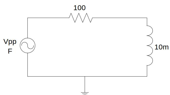
Fig. 6.1.1 RL circuit
The voltage and the current in the coil can be analysed over the circuit. Both their amplitudes and the out-of-phase between them may be tested on this circuit. Remember that you can measure the current at the beginning of each branch, it is here, before the resistor.
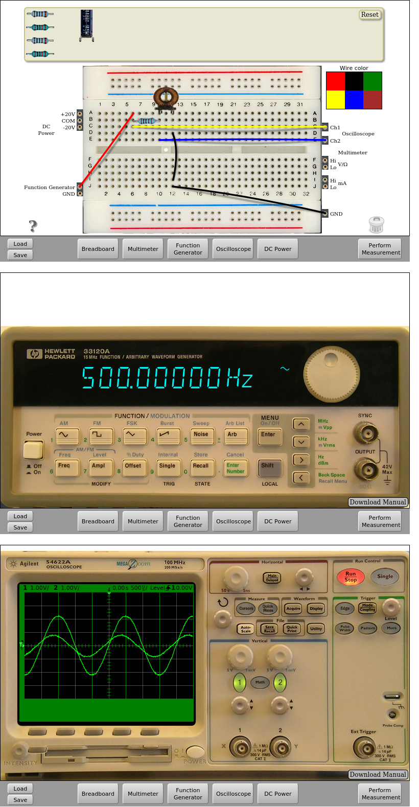
Fig. 6.1.2 Implementation of the RL circuit. Input signal: 500Hz and 3Vpp | Download this circuit
6.2. RLC circuit
For this circuit we are going to use the following components:
100Ω resistor
10mH inductor
2.2nF capacitor
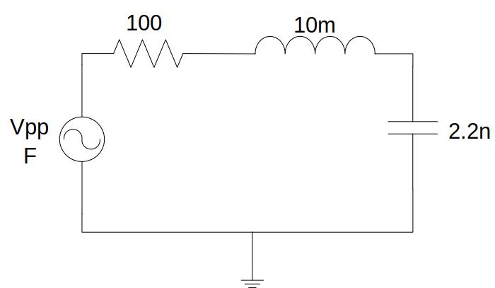
Fig. 6.2.1 RLC circuit
On this circuit it can be analysed how are voltages both in the capacitor and inductor respect to the input signal, being able to analyse both their amplitudes and the existing out-of-phase. Remember that you can measure the current at the beginning of each branch, it is here, before the resistor.
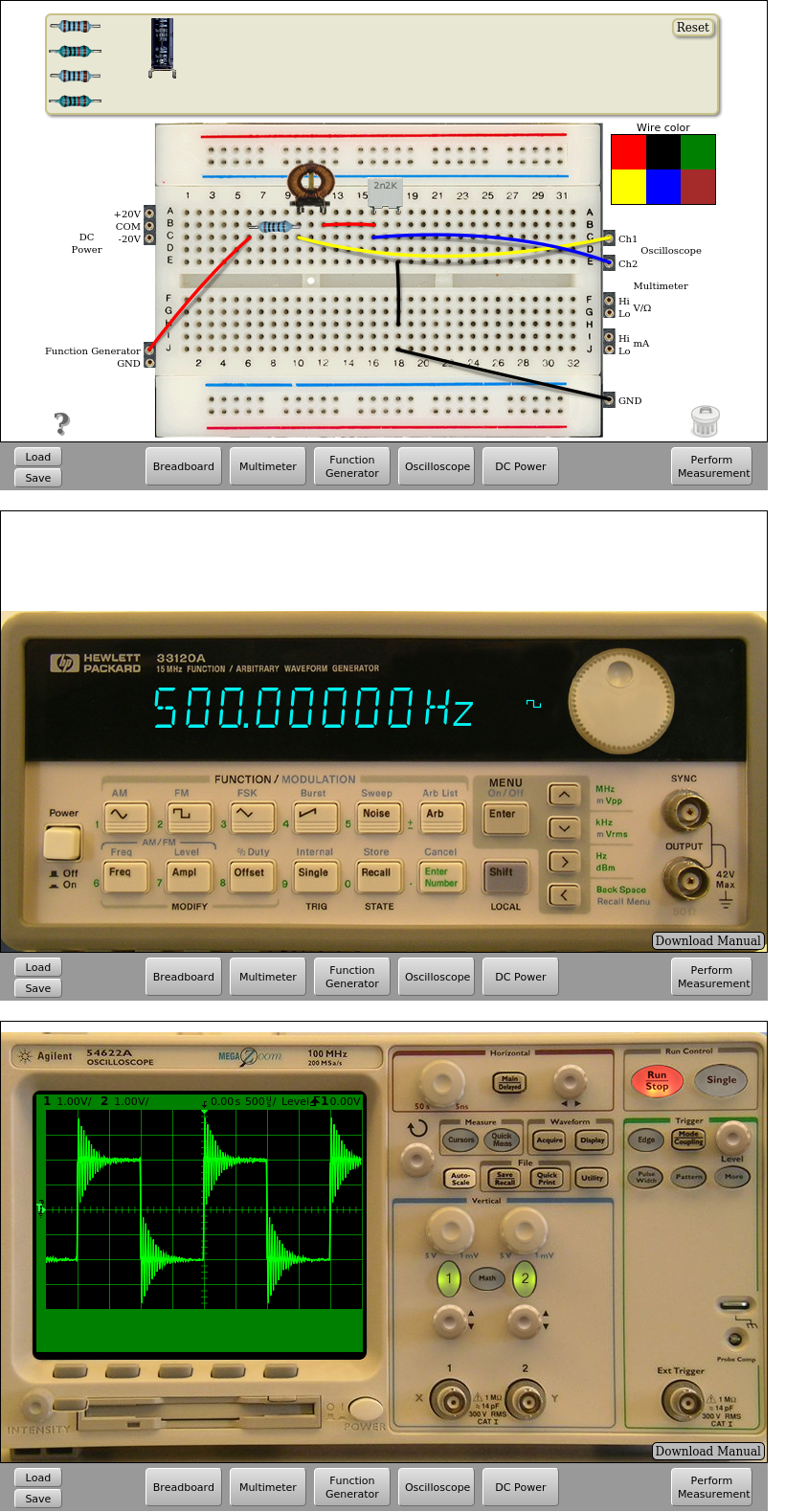
Fig. 6.2.2 RLC circuit implementation. Square input signal 500Hz and 2Vpp | Download this circuit
That’s all in RCL Circuits. Continue in Operational Amplifiers.