
5. RC Circuits
Note
This is part of the LabsLand Electronics laboratory documentation for educators using VISIR.
If you are interested in the next-generation version of this laboratory, the LabsLand Hive, please go to:
Or this same document in the Hive version:
https://labsland.com/pub/docs/experiments/hive/en/rc_circuits.html
5.1. Analysis of capacitor charge and discharge
The Analog Electronic remote lab allows to analyse and calculate the charge and discharge times of a capacitor (constant τ). The available components are: • 1 resistor of 1Ω and other of 10kΩ • Capacitors of 1uF, 10uF and 0.1uF To carry out the experiment, components can be connected as follows:
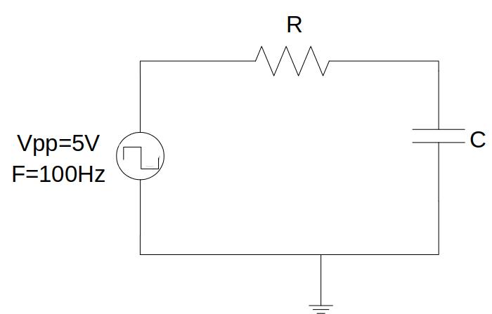
Fig. 5.1.1 Circuit to analyse the charge and discharge of the capacitor.
By connecting the function generation to the input of the circuit and setting up to generate a square signal of 5Vpp and F = 100Hz, it is possible to observe signals at the input and at the output on the oscilloscope. Assuming 1kΩ and 1uF, the capacitor charge constant will be τ = R · C = 1 ms.
It is considered that the capacitor is charged when the voltage dropped in the capacitor is equal to 63% of the final value. If the signal is 10Vpp, this value will be 6.3V. As the generated signal goes from -5V to + 5V, this value measured on the oscilloscope will be 1.3V. Analogously, its discharge value will be -1.3V.
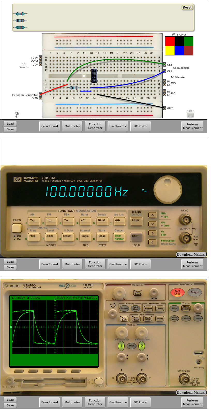
Fig. 5.1.2 Implementation and measurement on the remote lab | Download this circuit
5.2. Low pass and high pass RC filters
Using the remote laboratory, it is possible to check the operation of low pass and high pass RC filters.To this end the remote laboratory has of:
• 1 resistor of 1kΩ and other of 10kΩ
• Capacitors of 1uF, 10uF and 0.1uF
In order to perform the experiment, the components can be connected as shown in the figures below.
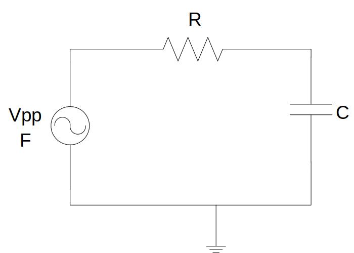
Fig. 5.2.1 Low pass filter
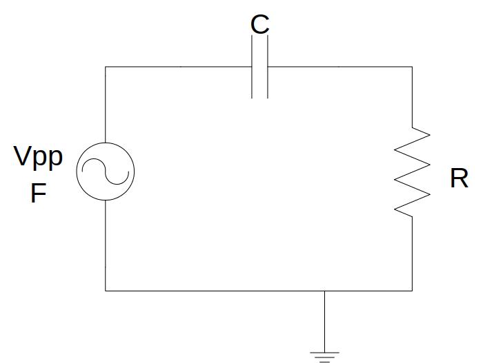
Fig. 5.2.2 High pass filter
The values of R and C can be combined as you like, giving rise to up to 6 different filters, each with a different cut-off frequency. Keeping the input signal voltage Vpp and varying its frequency, you can check the frequency response of the filter, for example, calculating its cut-off frequency.
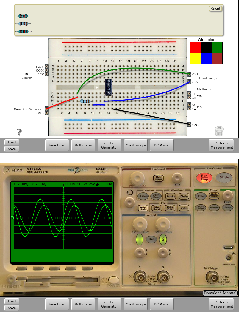
Fig. 5.2.3 Low pass filter implementation R=1kΩ and C=1uF. Input frequency = 160Hz. | Download this circuit
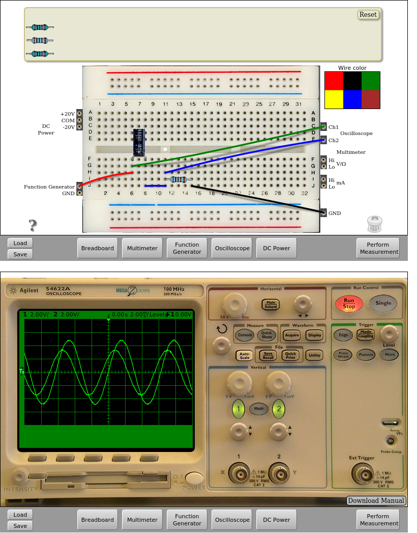
Fig. 5.2.4 High pass filter implementation R=1kΩ and C=1uF. Input frequency = 160Hz. | Download this circuit
That’s all in RC Circuits. Continue in RLC Circuits.