
3. Circuits with resistors
Note
This is part of the LabsLand Electronics laboratory documentation for educators using VISIR.
If you are interested in the next-generation version of this laboratory, the LabsLand Hive, please go to:
Or this same document in the Hive version:
https://labsland.com/pub/docs/experiments/hive/en/circuits_with_resistors.html
The analog electronic remote lab has a set of 4 resistors (2 resistor of 1kΩ and 2 resistor of 10kΩ) to build all the available configurations.
The election of these two values has not done under special criteria. The lab uses real components that are placed on the switching matrix, the instrument which is in charge of implementing the physical connections between the components and with the instruments, so it has a limited available space. Therefore, it is not possible to provide all the resistors’ values available on the market.
Even so, the learning outcome of these circuits is to experiment with different configurations (series, parallel) and experiment with the Ohm Law. Considerations to experiment with the Ohm Law:
In this circuits, the only available power supply is +25VDC
The maximum power supply value is +20VDC
The circuit always must be connected to ground.
Power supply always must be connected to ground.
Voltage measurements are available in all the nodes of the circuits.
Current measurements: due to a limited space on the switching matrix and the nature of this measure, current measurements are only allowed at the beginning of each branch in the circuit and in front of the first component of this branch 1.
3.1. Experiments with resistance associations
As it is indicated above, the following considerations must be taken into account when we work with resistances:
Only 2 resistances of 1k and 2 resistances of 10k can be used simultaneously
Any possible combination can be made. The circuits given below are only a set of examples.
3.1.1. Series circuits
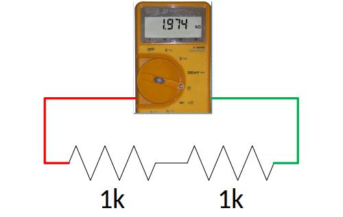
Fig. 3.1.1 2 resistors of 1kΩ in series: circuit.
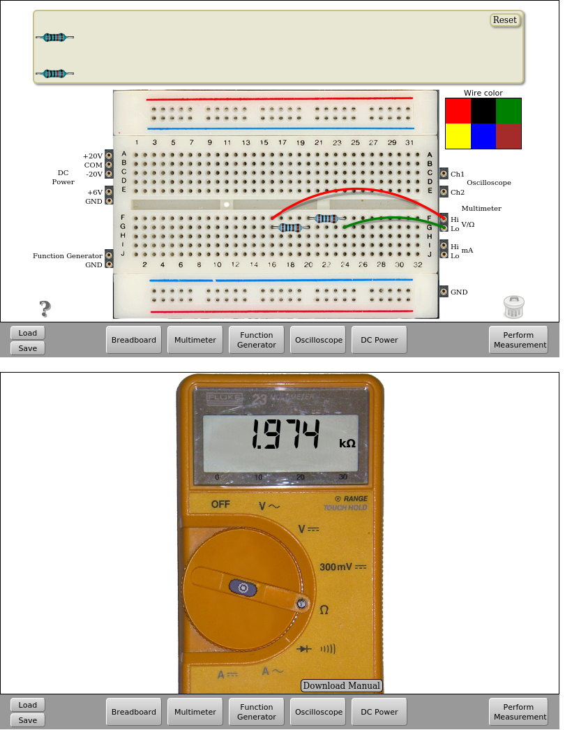
Fig. 3.1.2 2 resistors of 1kΩ in series: implementation. | Download this circuit
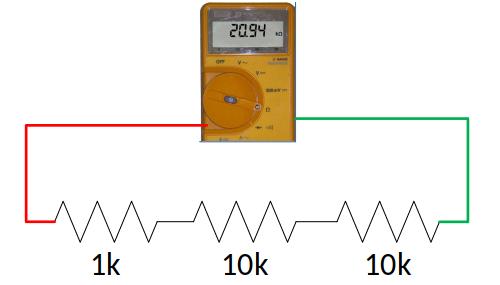
Fig. 3.1.3 1 resistor of 1kΩ in series with 2 resistors of 10kΩ: circuit.

Fig. 3.1.4 1 resistor of 1kΩ in series with 2 resistors of 10kΩ: implementation. | Download this circuit
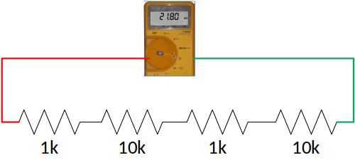
Fig. 3.1.5 2 resistors of 1kΩ in series with 2 resistors of 10kΩ: circuit.

Fig. 3.1.6 2 resistors of 1kΩ in series with 2 resistors of 10kΩ: implementation. | Download this circuit
Remember that the components are real, so their values, according to the manufacturer have some tolerance. That is why, for example, in the circuit described at Fig. 3.1.1, the measured value is not exactly 2kΩ but 1,974kΩ If the values of the available 1k resist resistors are measured, their values are approximately 986.5Ω and 988.2Ω hence the parallel equivalent is not exactly 2kΩ.
3.1.2. Parallel circuits
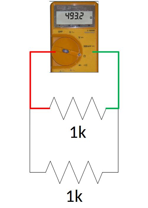
Fig. 3.1.7 2 resistors of 1kΩ in parallel: circuit.
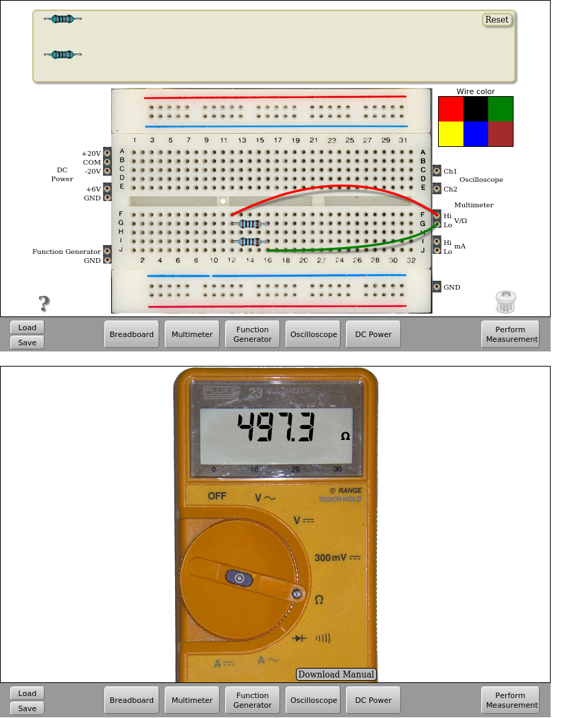
Fig. 3.1.8 2 resistors of 1kΩ in parallel: implementation. | Download this circuit
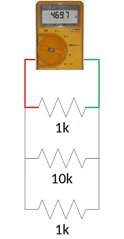
Fig. 3.1.9 2 resistors of 1kΩ in parallel with one of 10kΩ: circuit.
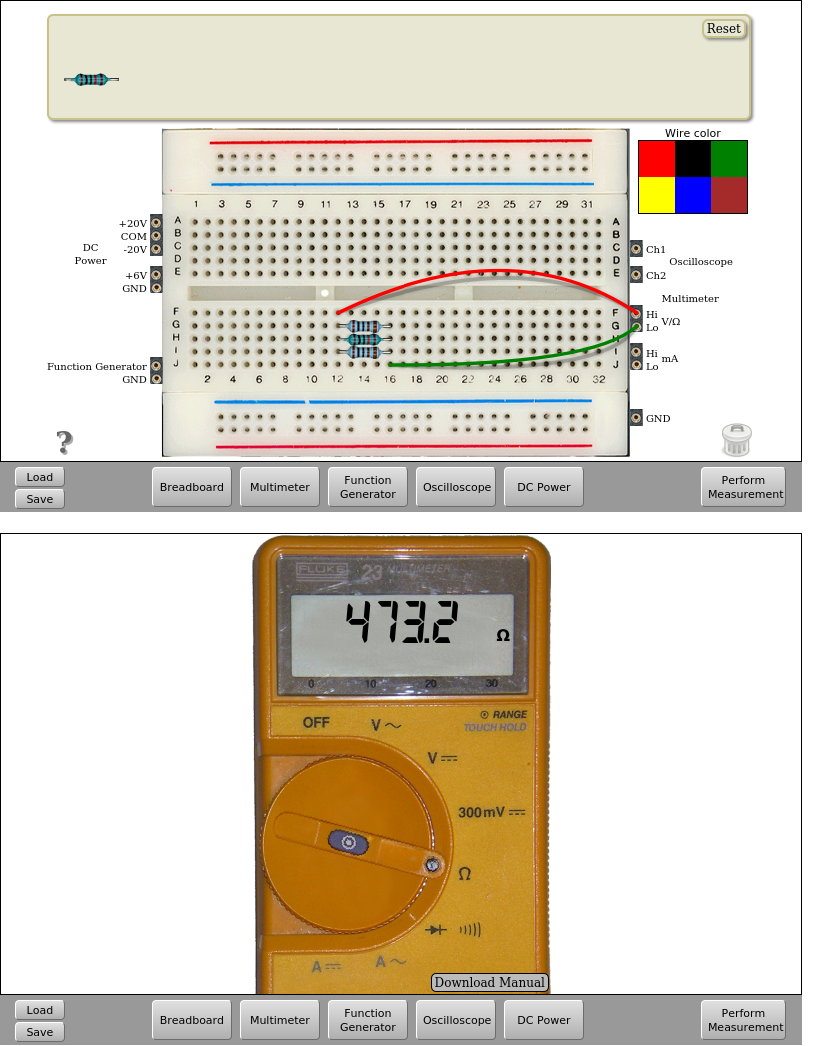
Fig. 3.1.10 2 resistors of 1kΩ in parallel with one of 10kΩ: implementation. | Download this circuit
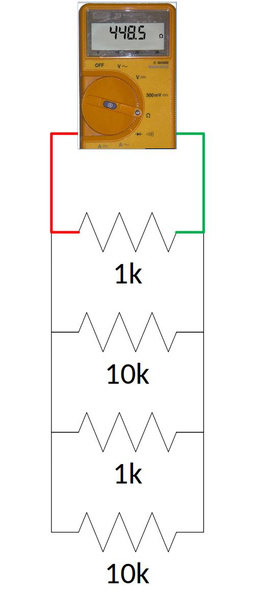
Fig. 3.1.11 2 resistors of 1kΩ in parallel with 2 resistors of 10kΩ: circuit.

Fig. 3.1.12 2 resistors of 1kΩ in parallel with 2 resistors of 10kΩ: implementation. | Download this circuit
As in the case of the series association of resistors, they can be connected in the desired order, remembering that a maximum of 2 resistances of 1kΩ and 2 resistors of 10kΩ can be used at the same time.
3.1.3. Series and parallel circuits
The remote analog electronics lab also allows you to create circuits combining serial and parallel associations. Here are some examples.
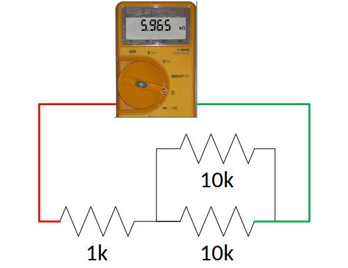

Fig. 3.1.13 Example of series and parallel | Download this circuit
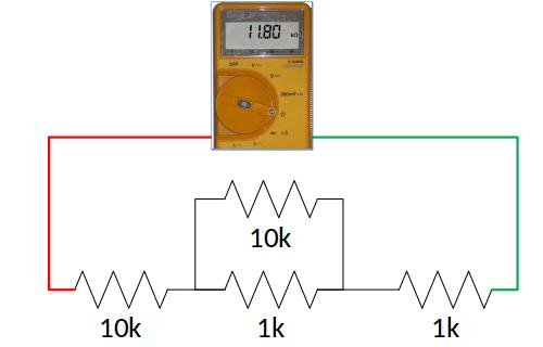

Fig. 3.1.14 Example of series and parallel | Download this circuit
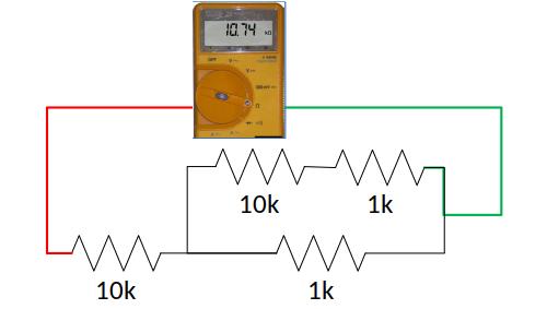

Fig. 3.1.15 Example of series and parallel | Download this circuit
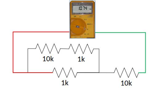

Fig. 3.1.16 Example of series and parallel | Download this circuit
3.2. Experiments with the Ohm’s Law
In this set of experiments, we can use the same circuits built in the previous section, feeding them with a DC voltage and then, we can measure the voltage drop anywhere in the circuit. That is, you can create circuits with combinations up to 4 resistors (2 of 1kΩ and 2 of 10kΩ) as you want.
We will also be able to measure on the circuit the currents that flows by each branch. Remember that to perform this measurement the multimeter must be placed at the beginning of each branch to be measured, in front of the first branch component as shown by the example in Fig. 3.2.1.
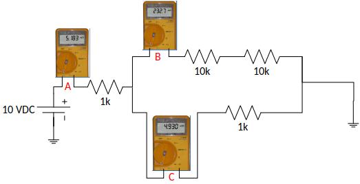
Fig. 3.2.1 Example for current measurement. See figures below.

Fig. 3.2.2 Implementation of the measurements at point A | Download this circuit
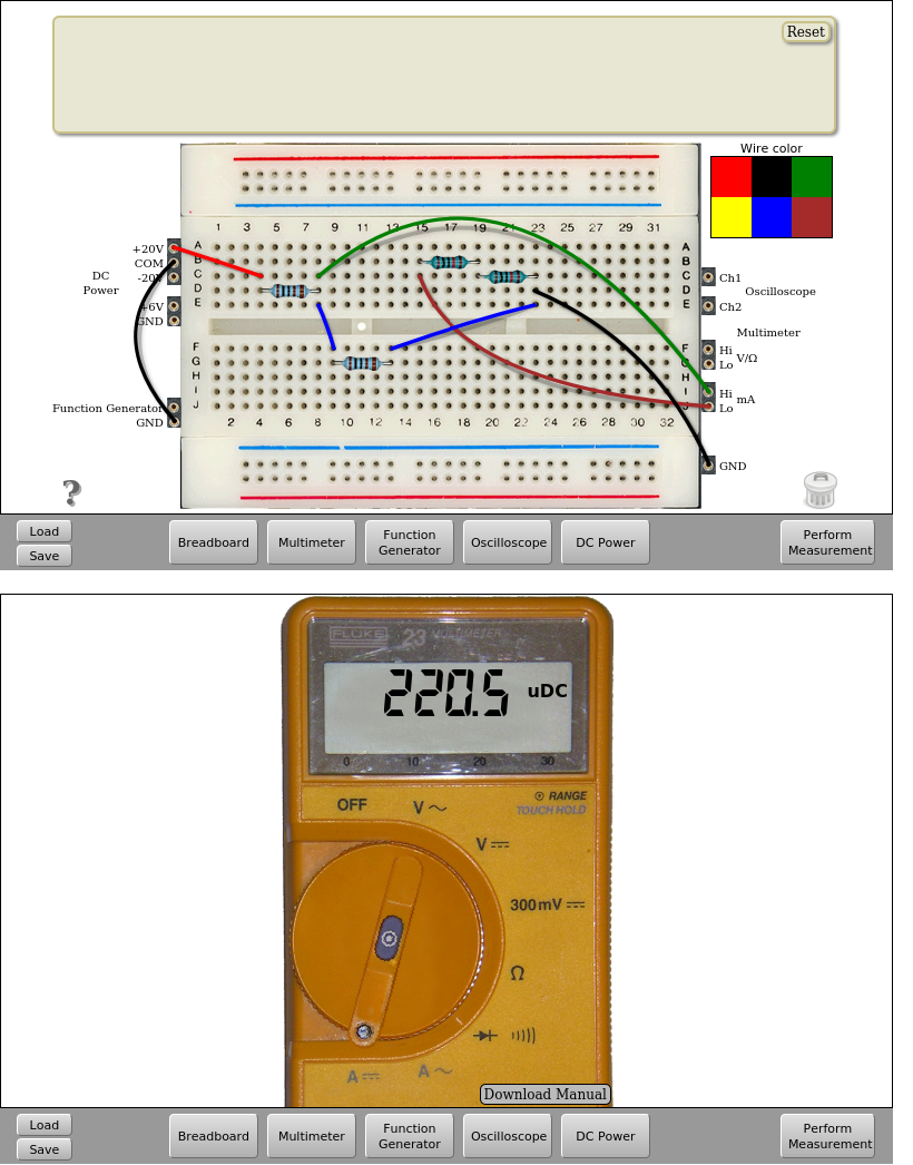
Fig. 3.2.3 Implementation of the measurements at point B | Download this circuit

Fig. 3.2.4 Implementation of the measurements at point C | Download this circuit
That’s all in Circuits with Resistors. Continue in Circuits with diodes.