
7. Circuits with operational amplifiers
Note
This is part of the LabsLand Electronics laboratory documentation for educators using VISIR.
If you are interested in the next-generation version of this laboratory, the LabsLand Hive, please go to:
Or this same document in the Hive version:
https://labsland.com/pub/docs/experiments/hive/en/opamps.html
Thanks to the Analog Electronics remote laboratory also it can be experienced with circuits more complex, including integrated circuits. They are listed some examples that can be implemented using operational amplifiers, specifically the U741, whose scheme appears in the figure below:
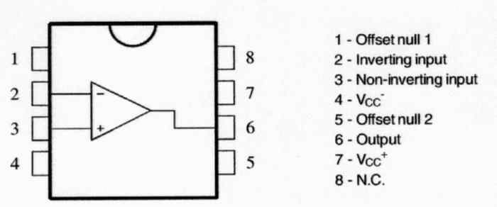
Fig. 7.1 UA741 integrated circuit
7.1. Non-inverting Operational Amplifier Configuration
Fig. 7.1.1 shows the electronic scheme of the UA741 op-amp operating as non-inverter amplifier. To check the effect of amplification, it is possible to change the resistance placed in the branch of feedback to take the values shown in Fig. 7.3.1.
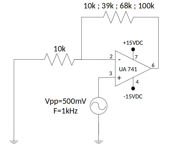
Fig. 7.1.1 Op-amp operating as non-inverter amplifier

Fig. 7.1.2 Implementation of op-amp operating as non-inverter amplifier, using 100kΩ | Download this circuit
Remember that the function generator generates a signal of double amplitude that sets it in its front panel. If you need a different configuration, let us know.
Very important: feed the circuit with + 15VDC -15VDC for correct operation.
7.2. Inverting amplifier
Fig. 7.2.1 shows the UA741 op amp electronic scheme working as inverter amplifier. To check the effect of amplification, it is possible to change the resistance placed in the branch of feedback to take the values shown in Fig. 7.3.1.
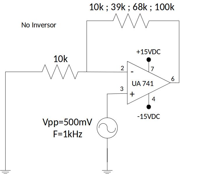
Fig. 7.2.1 Op-amp operating as inverter amplifier
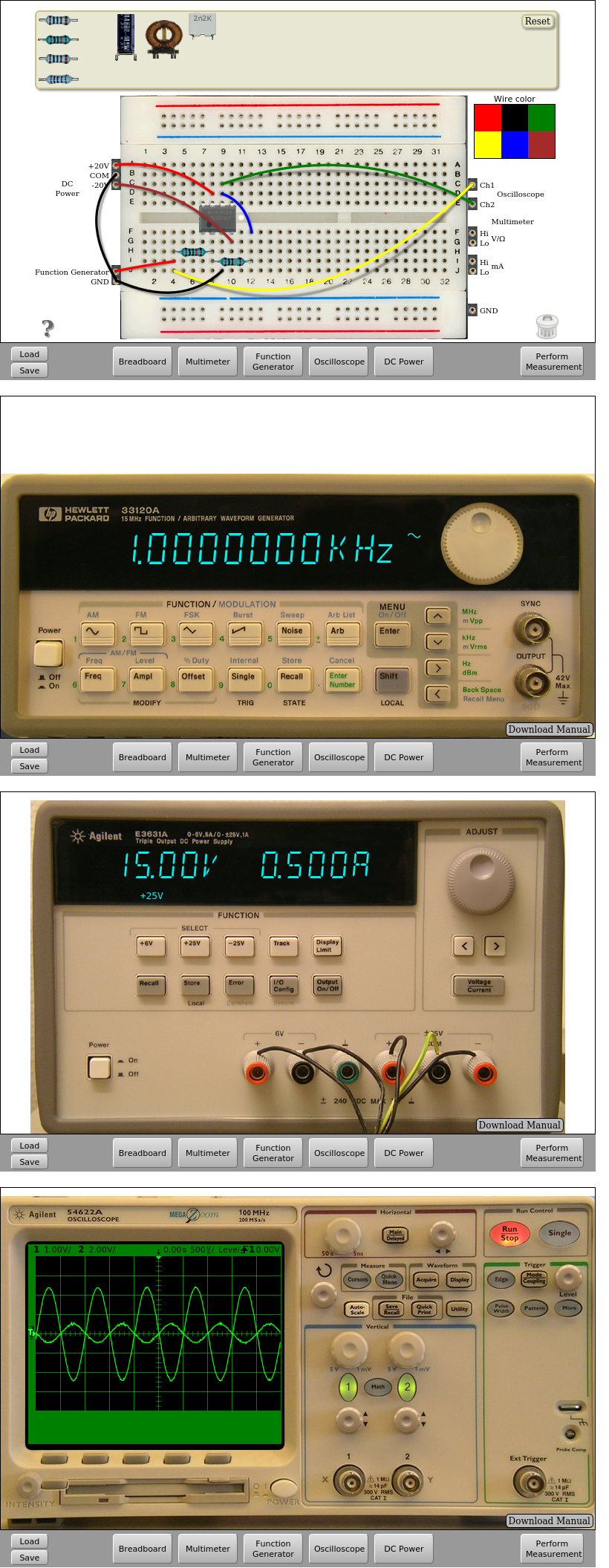
Fig. 7.2.2 Implementation of op-amp operating as inverter amplifier, using 100kΩ | Download this circuit
7.3. Op-amp Differentiator circuit
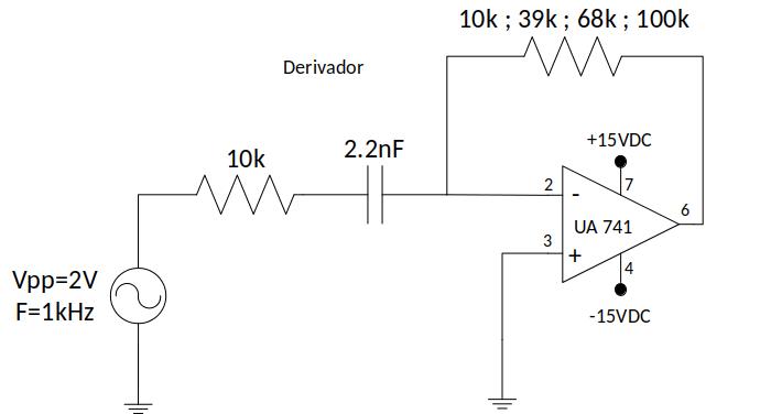
Fig. 7.3.1 Op-Amp Differentiator circuit
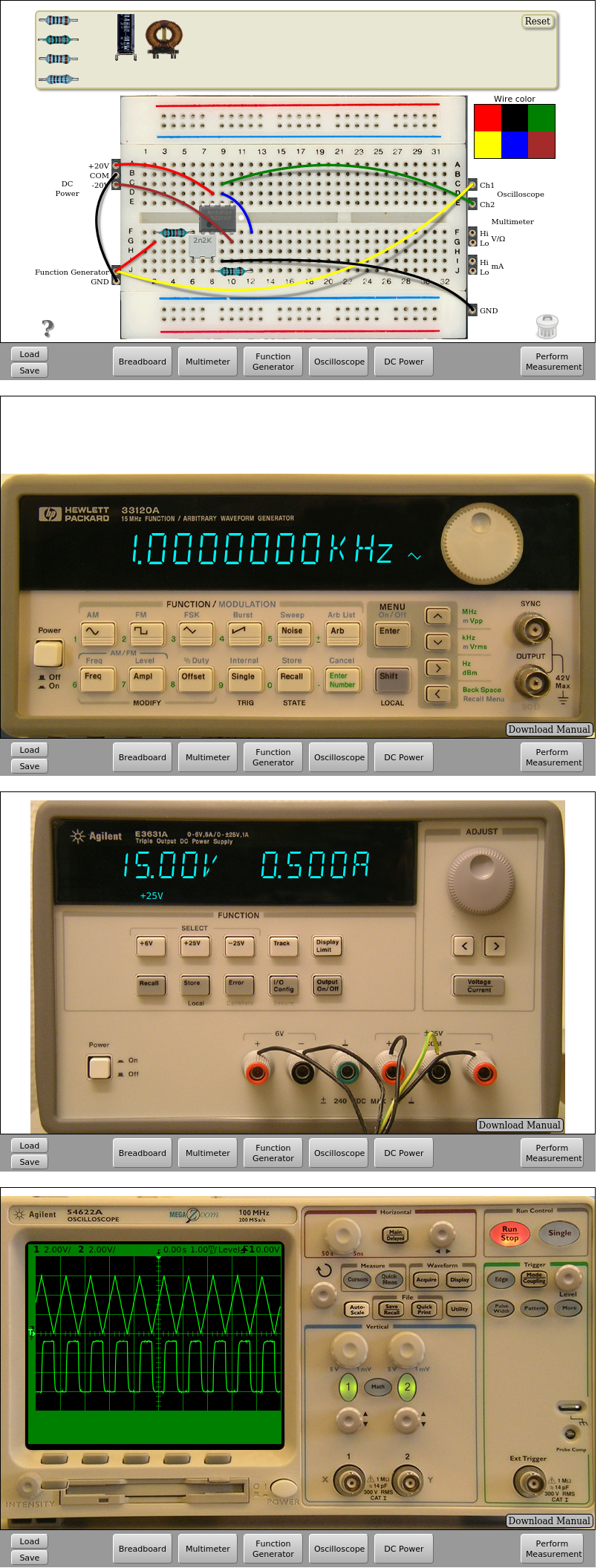
Fig. 7.3.2 Op-amp Differentiator circuit implementation, being R=100kΩ and a triangle input signal | Download this circuit
7.4. Op-amp Integrator circuit
Next figure shows the UA741 working as integrator amplifier. As in the previous circuits, the resistor connected on the feedback branch, can adopt the values shown at Fig. 7.4.1.
Fig. 7.4.1 Op-Amp Integrator circuit
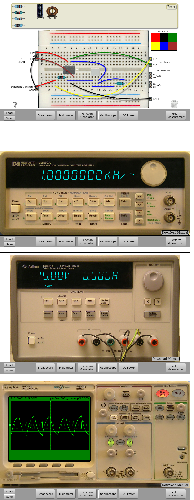
Fig. 7.4.2 Op-amp integrator circuit implementation, being R=100kΩ and a square input signal | Download this circuit
7.5. Op-amp Comparator circuit
Next figure shows the UA741 working as comparator. As in the previous circuits, the resistor connected on the feedback branch, can adopt the values shown at Fig. 7.5.1.
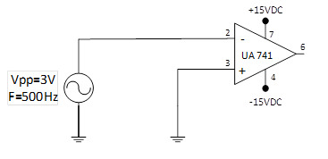
Fig. 7.5.1 Op-Amp comparator circuit
Fig. 7.5.2 Op-amp comparator circuit implementation | Download this circuit
That’s all in Operational Amplifiers. Continue in Circuits with transistors.