4. Circuits with diodes
Note
This is part of the LabsLand Electronics laboratory documentation for educators using VISIR.
If you are interested in the next-generation version of this laboratory, the LabsLand Hive, please go to:
Or this same document in the Hive version:
https://labsland.com/pub/docs/experiments/hive/en/circuits_with_diodes.html
The components available for experimenting with diodes are:
1 1N4007
1 Zener 5.1V
Resistors of 1kΩ and 10kΩ
Capacitors of 1uF, 10uF and 0.1uF
4.1. Diode characteristic curve
The VISIR remote laboratory can be used to obtain the diode characteristic curve. In this experience it can be verified what it happens when the diode is polarized in direct and in reverse. For that:
Carry out the following assembly
Set the supply voltage. Use the + 25VDC source.
Measure the voltage drop on the diode
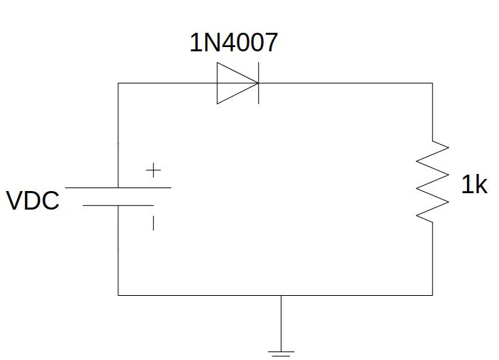
Fig. 4.1.1 Circuit to obtain the characteristic curve of the diode
Implementation on the remote laboratory:
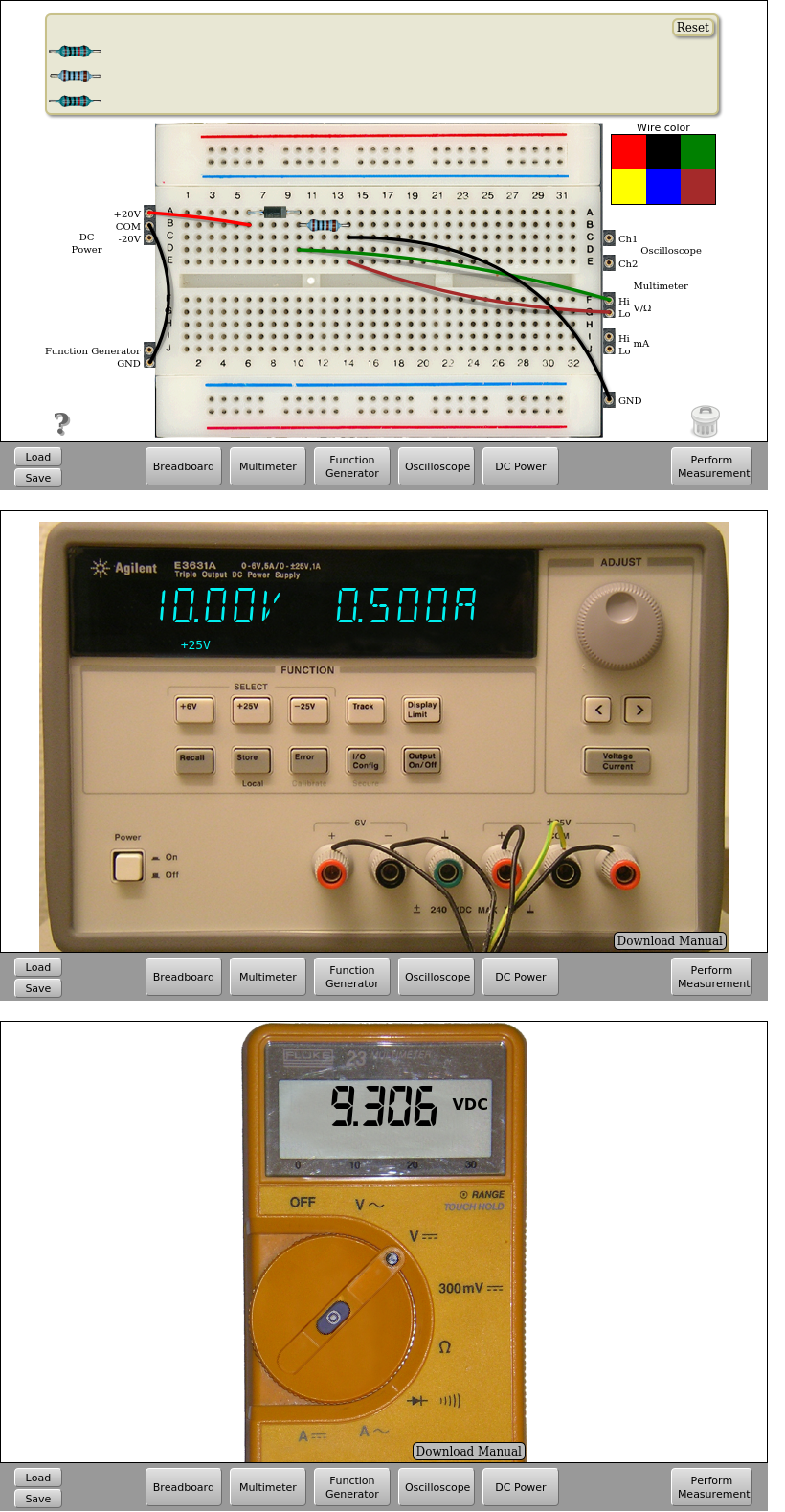
Fig. 4.1.2 Implementation on the remote lab. Diode in direct possition | Download this circuit
In this circuit it is also possible to measure the current flowing through the diode. To do this, connect the multimeter between the diode and the resistor or before the diode.
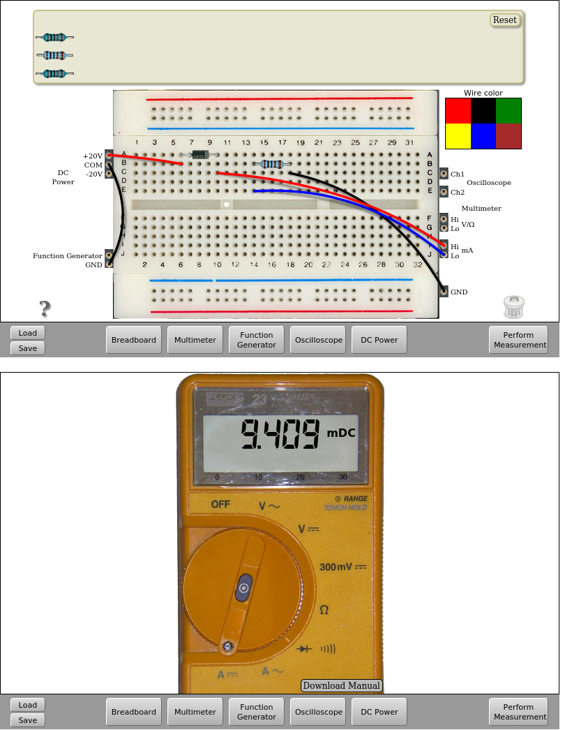
Fig. 4.1.3 Measuring the current ton the diode. VDC=+10V | Download this circuit
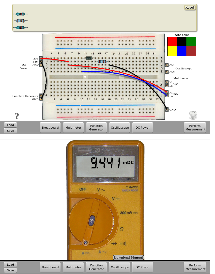
Fig. 4.1.4 Measuring the current ton the diode. VDC=+10V | Download this circuit
4.2. Half-wave rectifier
If, in the previous circuit, the DC source is replaced by the function generator and the circuit is supplied with a sinusoidal signal, we can observe the operation as a half-wave rectifier.
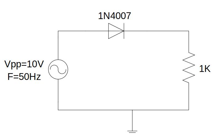
Fig. 4.2.1 Half-wave rectifier
In the circuit above, the diode can be connected in direct or inverse and observe how the diode rectifies the positive or negative half-cycle of the input signal in each case.
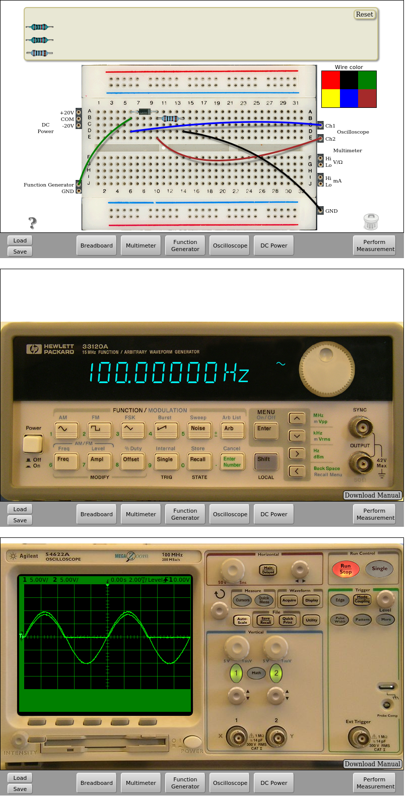
Fig. 4.2.2 Implementation on the remote lab of the positive half-wave rectifier (10.0 VPP, 100 Hz) | Download this circuit
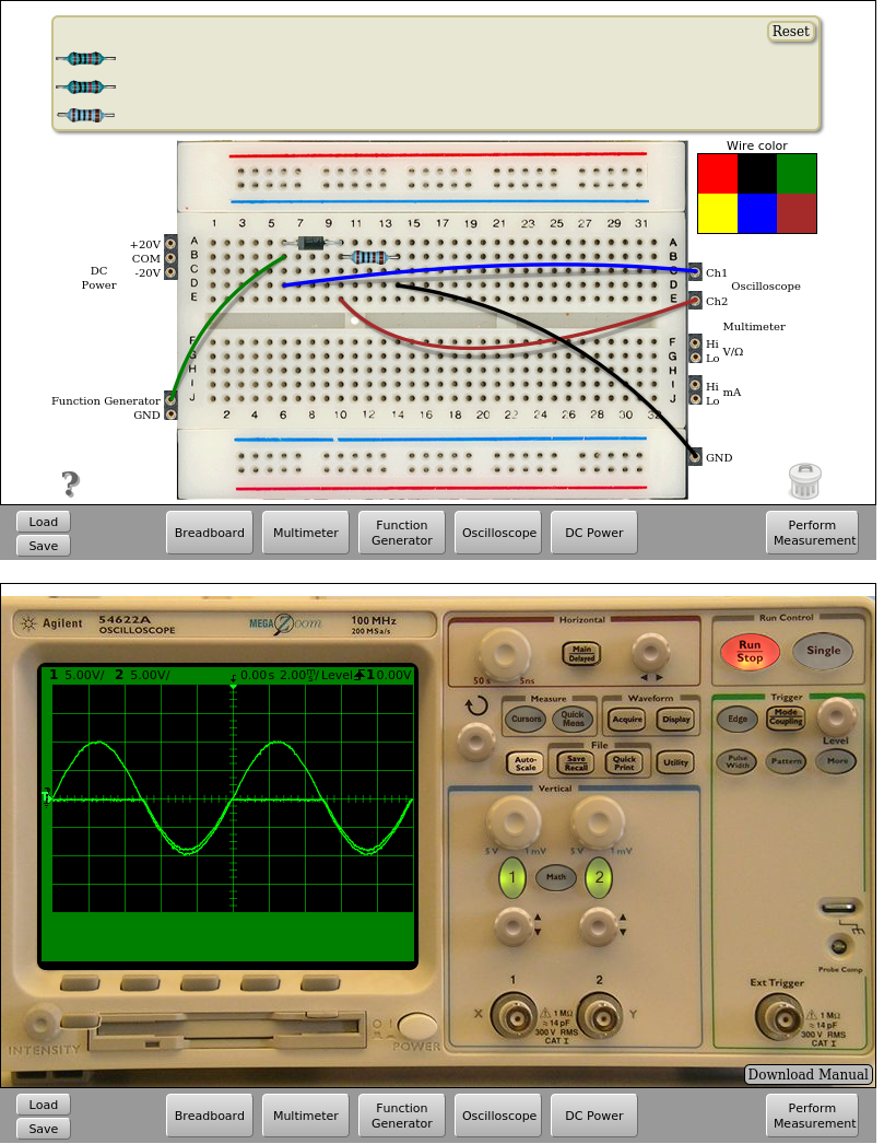
Fig. 4.2.3 Implementation on the remote lab of the negative half-wave rectifier (10.0 VPP, 100 Hz) | Download this circuit
4.3. Half-wave rectifier with output filter
A low-pass filter can be added to the previous circuit at the output to obtain a continuous signal. To do this, simply add a capacitor in parallel to the 1kΩ resistor. The available capacitor values are 1uF, 10uF and 0.1uF.
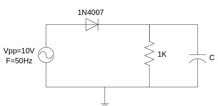
Fig. 4.3.1 Half-wave rectifier with output filter circuit
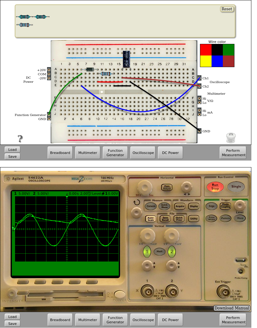
Fig. 4.3.2 Implementation on the remote lab of the half-wave rectifier with output filter (Function generator as before: 10.0 VPP, 100 Hz) with C=10uF. | Download this circuit
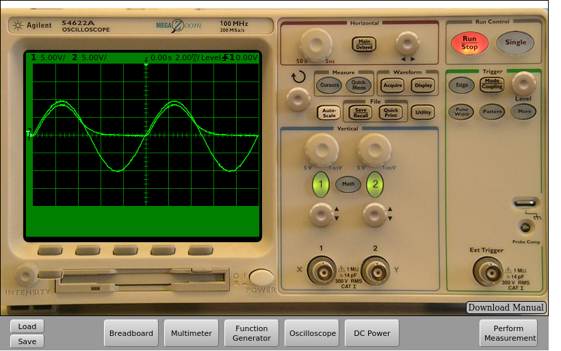
Fig. 4.3.3 Implementation on the remote lab of the half-wave rectifier with output filter, but using C=1uF. | Download this circuit
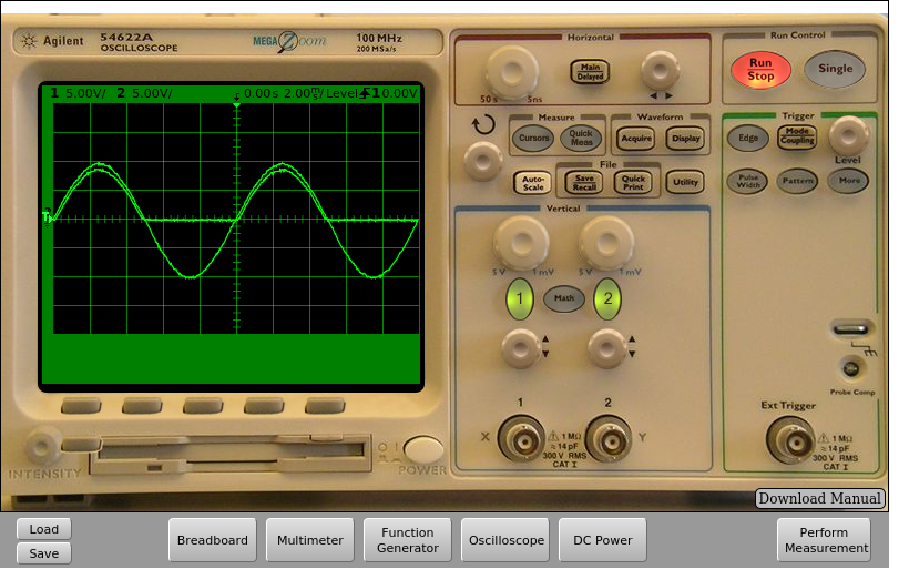
Fig. 4.3.4 Implementation on the remote lab of the half-wave rectifier with output filter, but using C=0.1uF. | Download this circuit
4.4. Zener diode voltage regulator
Through this experiment the operation of a Zener diode can be analysed, either with forward or reverse polarization. For this, the remote laboratory has a 5.1V Zener diode, a 470Ohms resistor and a 1k resistor, which can be connected to the configuration shown at Figure 11, in which the diode can be removed and see how it affects the voltage drop between both resistors.
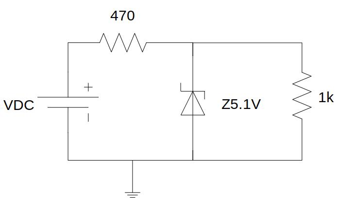
Fig. 4.4.1 Circuit with Zener diode
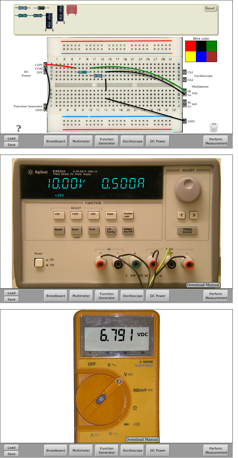
Fig. 4.4.2 Implementation on the remote lab | Download this circuit
In the previous circuit it is also possible to connect the multimeter before the 470 ohms resistor and in front of the Zener diode to obtain its characteristic I-V curve varying the value of the supply voltage VDC and taking measures of voltage and intensity on the circuit.
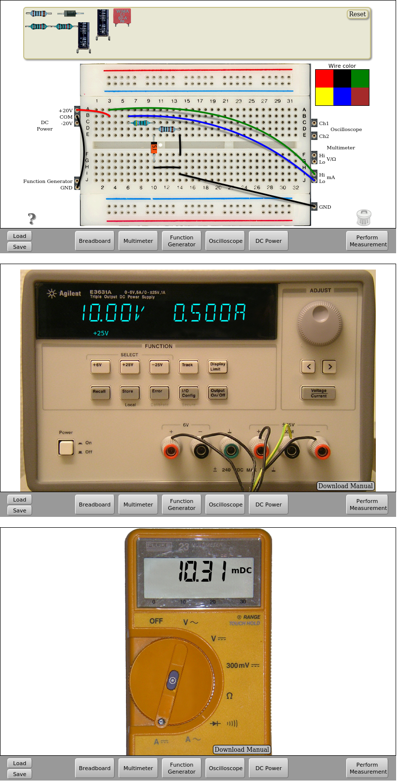
Fig. 4.4.3 Measure of the currents on the Zener circuit (1) | Download this circuit
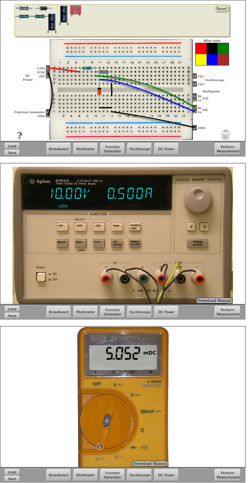
Fig. 4.4.4 Measure of the currents on the Zener circuit (2) | Download this circuit
That’s all in Circuits with Diodes. Continue in RC Circuits.
