
6. RLC circuits
Note
This is part of the LabsLand Electronics laboratory documentation for educators using the LabsLand Hive. If you want to use this lab in class, check Use this laboratory in class.
6.1. Basic RL circuit
For this circuit we are going to use the following components:
100Ω or 470Ω resistors
10mH coil
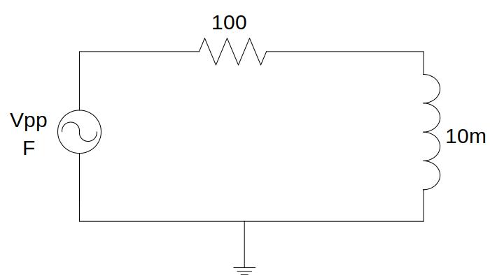
Fig. 6.1.1 RL circuit
The voltage and the current in the coil can be analysed over the circuit. Both their amplitudes and the out-of-phase between them may be tested on this circuit. Remember that you can measure the current at the beginning of each branch, it is here, before the resistor.
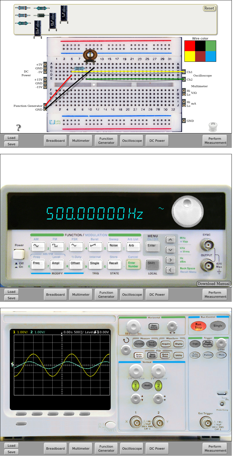
Fig. 6.1.2 Implementation of the RL circuit. Input signal: 500Hz and 3Vpp | Download this circuit
6.2. RLC circuit
For this circuit we are going to use the following components:
100Ω resistor
10mH inductor and 100mH inductor
2.2nF capacitor
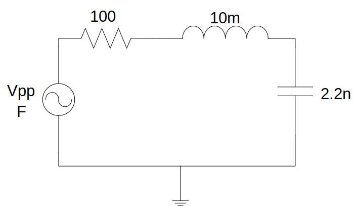
Fig. 6.2.1 RLC circuit
On this circuit it can be analysed how are voltages both in the capacitor and inductor respect to the input signal, being able to analyse both their amplitudes and the existing out-of-phase. Remember that you can measure the current at the beginning of each branch, it is here, before the resistor.
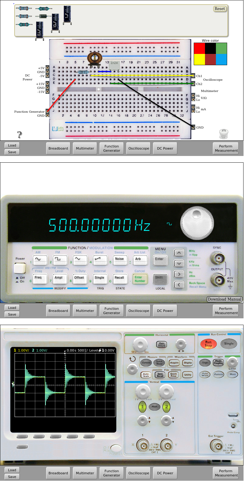
Fig. 6.2.2 RLC circuit implementation. Square input signal 500Hz and 2Vpp and 100 ohm resistor. 10mH. | Download this circuit
With an 100mH inductor, the result is the following:

Fig. 6.2.3 RLC circuit implementation. Square input signal 500Hz and 2Vpp and 100 ohm resistor. 100mH. | Download this circuit
That’s all in RCL Circuits. Continue in Operational Amplifiers.