
8. Circuits with transistors
Note
This is part of the LabsLand Electronics laboratory documentation for educators using VISIR.
If you are interested in the next-generation version of this laboratory, the LabsLand Hive, please go to:
Or this same document in the Hive version:
https://labsland.com/pub/docs/experiments/hive/en/transistors.html
In the remote laboratory, it is also possible to implement circuits with transistors, as it picks up the example of the Fig. 8.1.
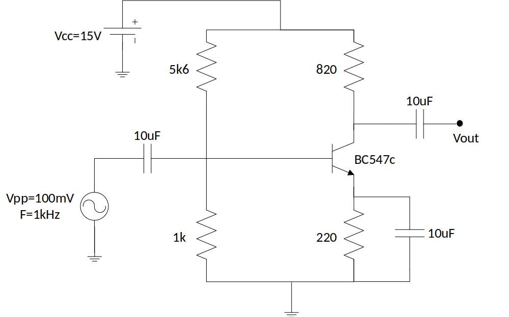
Fig. 8.1 BJT in common emitter configuration
The implementation of the circuit in the remote laboratory is shown in Fig. 8.2. Voltage measurements can be performed in all the nodes of the circuit, as well as obtain the output signal with respect to the input signal, as it is shown in Fig. 8.2.
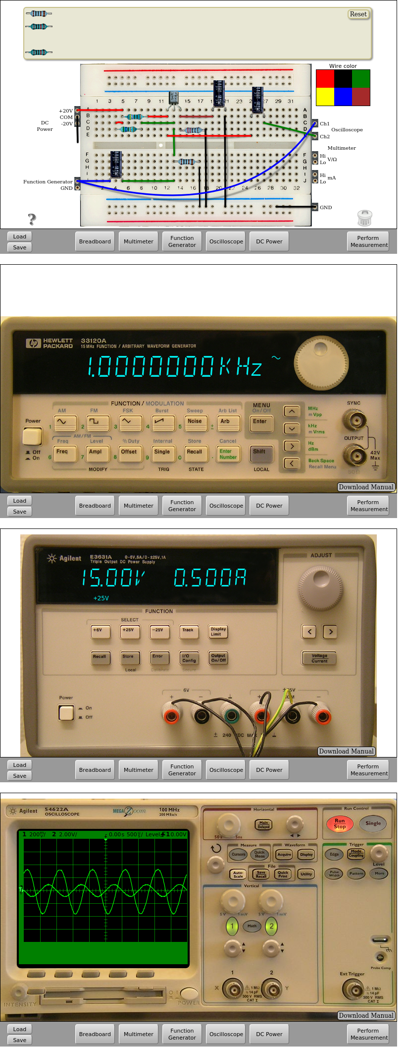
Fig. 8.2 Implementation of the BJT common emitter circuit | Download this circuit