The LabsLand FPGA laboratory lets you experiment with hardware description languages, such as Verilog or VHDL. This can be done easily, and it is possible to immediately apply your code to real hardware. It’s very fast and easy to get started, and you need no equipment or installation beyond a common Internet browser.
Very often, to get started, teachers or students will want to adapt pre-existing code or educational practices that they already have for specific FPGA boards, or from various sources. This is generally easy, as long as the involved peripherals are supported by LabsLand, and as long as you take some things into account. In this article, we detail how to do it.
The traditional process to learn VHDL or Verilog
To learn hardware description languages such as VHDL or Verilog, normally students will have to buy or get access to an educational FPGA board made by some vendor. For example, the Terasic Altera DE2-115 boards, or the Altera DE1-SoC boards (with Altera FPGAs), or the Digilent Basys-3 Artix-7 (with Xilinx FPGAs). Then, if students want to use it with their own computer, they will have to install the various vendor tools. In the case of Altera boards, for instance, they would normally install some version of Quartus. In the case of the Basys-3 board, Xilinx Vivado would most likely be the case. Or ISE WebPack in the case of older boards.
All those are very complete and powerful tools, but at the same time they are very complex. Sometimes they require licenses, and almost invariably, they will have high hardware requirements. It is not strange that they require over 15-20 gigabytes of hard-drive space, and that they are not available for certain Operative Systems.
Some advantages of the LabsLand FPGA laboratory
The LabsLand FPGA remote labs can provide various advantages. The most obvious, of course, is that students will not have location or time restrictions. They will no longer need to go to a lab that is only open certain hours, and they will no longer require someone to supervise such a lab. They will be able to practise with real FPGA boards when and wherever they want. Most often, the traditional hands-on laboratory won’t be replaced. Instead, the remote lab will complement it, and teachers will be able to leverage both tools to provide their students with a high-quality practical education in the most effective way.
Other significant advantage is that the FPGAs, VHDL or Verilog learning process becomes much easier. Students no longer need to purchase a FPGA board, or wait for their university to lend them one. They no longer need to wait to receive the package. And they no longer need to install a large and complex production-oriented vendor software, that very often will not be supported by their PC, or for which they will not have licenses. Instead, students will be able to design their logic and test it remotely against a real FPGA, in just minutes. Using simply a web platform, with no installation, and through remote but absolutely real hardware.
Using a pre-determined constraints file (e.g. QSF)
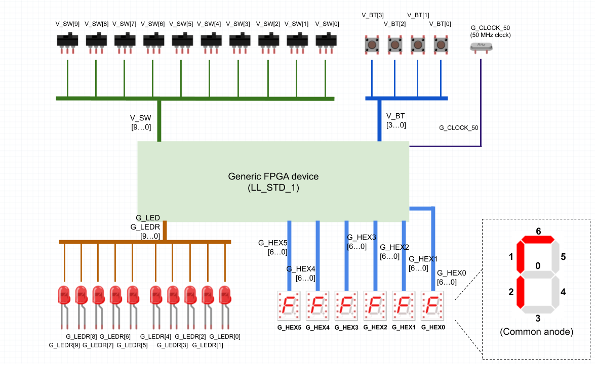
One of the peculiarities of the LabsLand FPGA laboratory is that rather than forcing the students to create a constraints file (such as Altera’s QSF files) it relies on a particular fixed constraints file. The LabsLand FPGA laboratory has several input and output peripherals, and is not designed or intended for its hardware to be modified by the students. This is what makes this approach make sense. It implies, however, that students will need to take into account in their designs which hardware is available and how the different signals are declared within the provided constraints file.
In the various available lab configurations, the constraints file is always available through the Documentation section, in the lower left corner of the screen, which can be accessed from the IDE itself. We show in the next picture.
For example, most FPGA educational boards, such as Altera’s DE2-115 or DE1-SoC, or Xilinx’ Basys3, have LEDs. Typically, in the provided constraints file LEDs will be declared as G_LED vector, of type std_logic_vector. The “G” comes from “generic”, as LabsLand normally will use the same name for all boards that include LEDs, for uniformity.
Other example are switches, that will normally be declared as V_SW with a type of std_logic_vector. This case, the V comes from “virtual” to emphasize the fact that they are not really the physical switches of the educational board, but an abstraction: virtual switches that can be controlled through the web interface, but whose signals are actually received from the real GPIO inputs of the board as if they were normal switches.
Adapting practices and pre-existing codes
The VHDL or Verilog codes that can be found in different places, such as vendor manuals or in open source repositories, will normally have a top entity that uses non-standard names. For example, a practice for a Finite State Machine will probably have a clock and a reset switch, and whoever created the original code will probably have declared those inputs with any kind of name. For example, “clk” for the clock or “rst” for the reset switch. But likewise, they could have used “clk50mhz” or “reset”. If this were a traditional hands-on practise using the standard vendor software, then the person trying that code would be expected to create a constraints file for those inputs and with those names so that the code works.
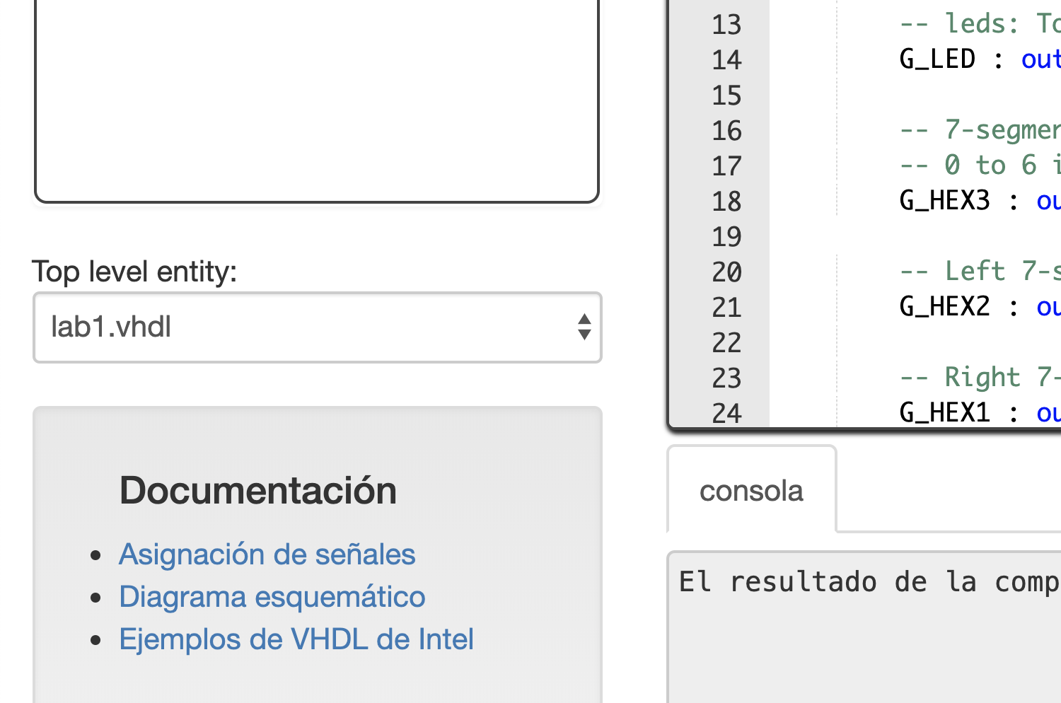
In the case of LabsLand the constraints file is fixed. This has the advantage that, therefore, students will not need to create it. It has the disadvantage that names will have to match. Thus, for external code to work, the teachers or students will need to replace the names (and sometimes the types) of the top entity signals so that they match LabsLand’s. This is not usually hard, because it only needs to be done to the top entity, and often it is even possible to just use the search and replace functionality of the web IDE by pressing CTRL+F. Normally, the time that is needed to adapt the code is lower than the time you would require to create a constraints file from scratch. But you do need to be somewhat careful.
In the next image we shot for example the diagram of one of the generic FPGA devices that are available in LabsLand. It includes the names for the inputs and outputs which are defined in the most common constraints file. The full constraints file is also available in the documentation of each lab.

Example with a Finite State Machine
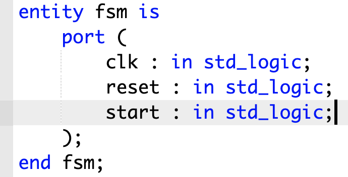
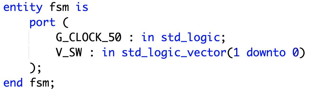
We can illustrate this, for instance, with an example of a finite state machine. Let’s pretend that we have found in a vendor manual an interesting FSM example, and that we want to test it with an Altera DE-1 board using the LabsLand FPGA laboratory.
We can observe, for example, that the top entity of the main code has, in this case, the following input signals:
- clk (std_logic)
- reset (std_logic)
- start (std_logic)
As we mentioned, normally we would have to create a matching QSF restrictions file. In the case of LabsLand FPGA, the constraints file is fixed. We will simply have to ensure that the signal names match the ones that the system expects (and their type too, sometimes).
For this, in this case, we will change the signals for the following:
- We will change the name of the “clk” signal to “G_CLOCK_50”. That is the name for the clock in the LabsLand Altera DE-1 lab (and in most similar labs); and it is connected to a 50 MHz clock.
- For the reset and start signals we want to use the first and last switches of the board, respectively. Thus we will change those inputs for “V_SW”, that matches the LabsLand FPGA inputs. It’s a std_logic_vector, so instead of using “reset” we will use V_SW(0) and instead of “start” we will use V_SW(1). That way, when we test the code, we will simply have to use the first and second switches in the UI so that everything works as intended.
Conclusions
As you can see, it’s relatively simple to adapt any VHDL or Verilog code, as long as the hardware supported by the laboratories is sufficient. You only need to adapt the top entity signals to the predefined ones. Either way, if you are reading these instructions and you have any difficulty or doubt, do not hesitate to contact us!