License LCAL9002
All real-time remote labs
Remote access to 16 laboratories included:
The equipment is always real, not a simulation. Access now. No need to wait for an equipment to be shipped.
Laboratories included in this license
 Arduino Board (code)
 Arduino Board (visual)
 Arduino robot (code)
- Arduino robot (visual)
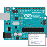 ATmega328p (Assembly)
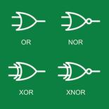 Boole Designer
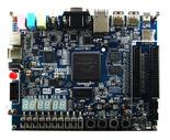 Digital Trainer
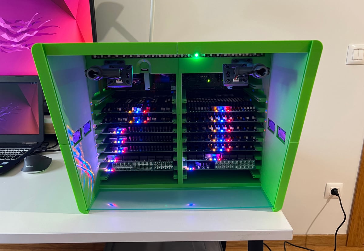 Electronics - Hive
 FPGA Laboratory
 DE1-SoC
- DE1-SoC (binary upload)
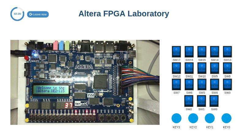
 Altera DE2-115
 STM32 Nucleo (C)
- STM32 Nucleo (No IDE)
- DE1-SoC · Nios V
- Intel DE2-115 (no IDE)
How does LabsLand work?
LabsLand is a global network of real laboratories available online. Students (in schools, universities and life-long learning platforms) can access the real laboratories through the Internet, using their laptop, tablet or phone.
In every case, the laboratory is always real (not simulated), and available through the Web (you do not need to obtain any hardware, deal with shipping, etc.).
Bulk licenses
If you are going to buy multiple licenses (e.g., for a classroom or group of users, or institutional license), contact us for discounts.
You buy LabsLand licenses as an individual in the links below, or for your institution. If you buy licenses for your institution, you have to reach out so we can provide you with a space for your institution where you can keep track of the usage by users and obtain other institution-focused tools.
Arduino Board (code)
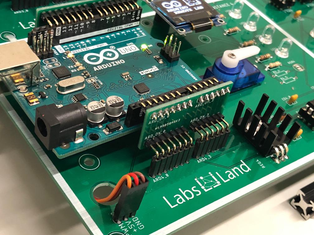
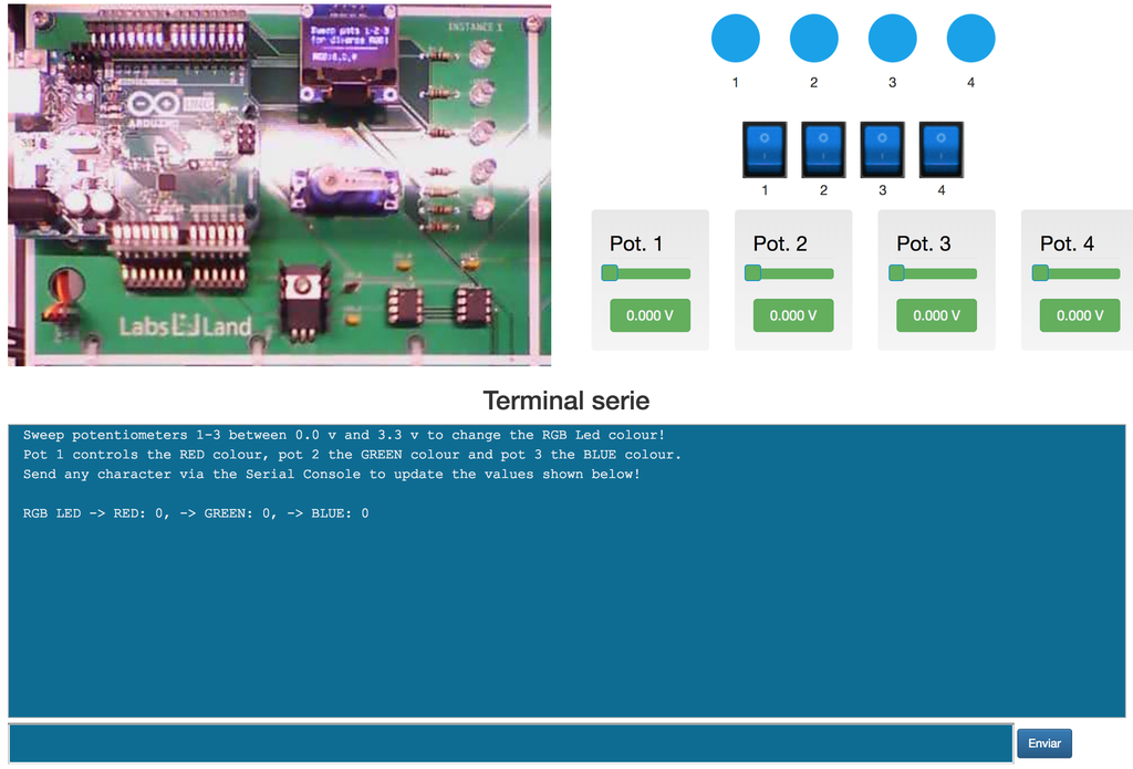
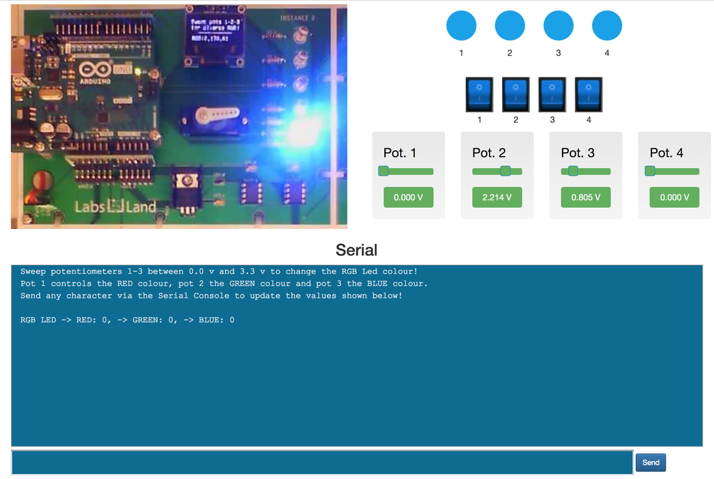
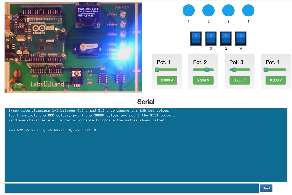
With this laboratory, you can program a real Arduino Uno board. It also includes several input and output peripherals, similar to those that are often included in Arduino starter kits.
Those peripherals include LEDs, switches, buttons, an OLED display, a servo motor, etc.

Arduino Board (visual)
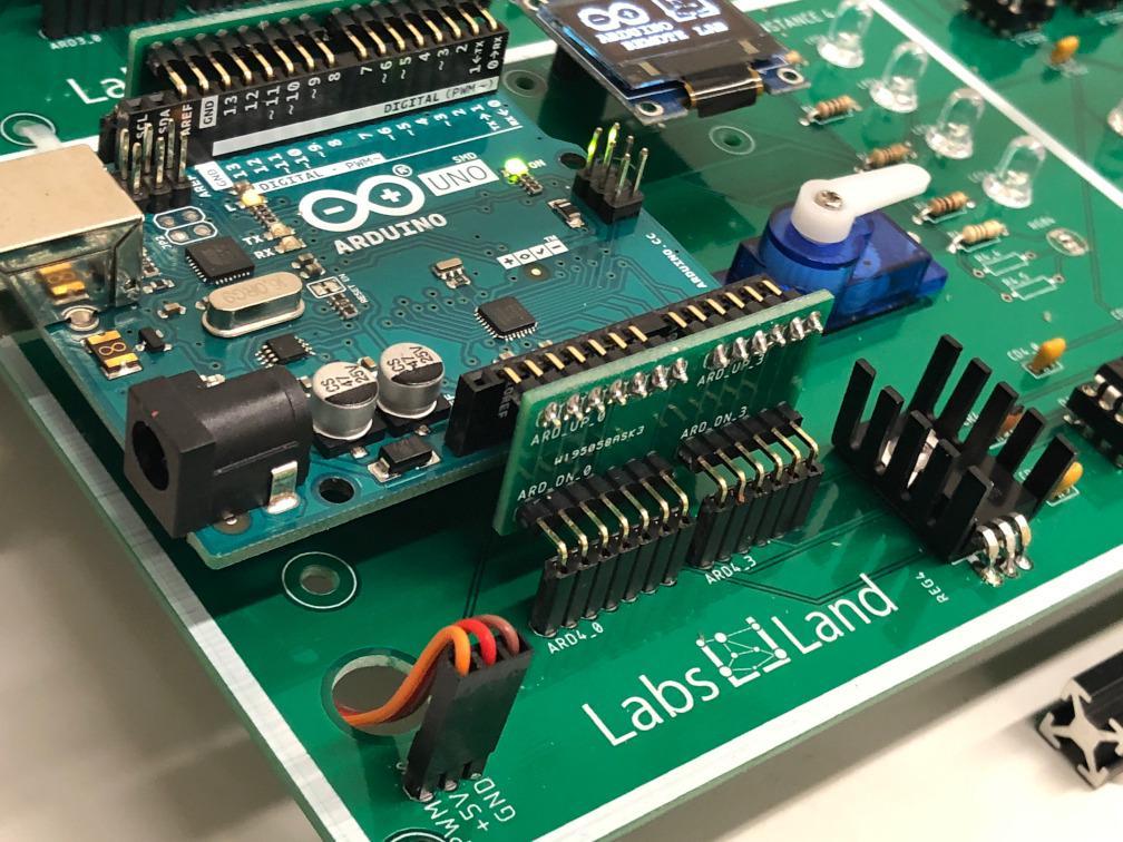
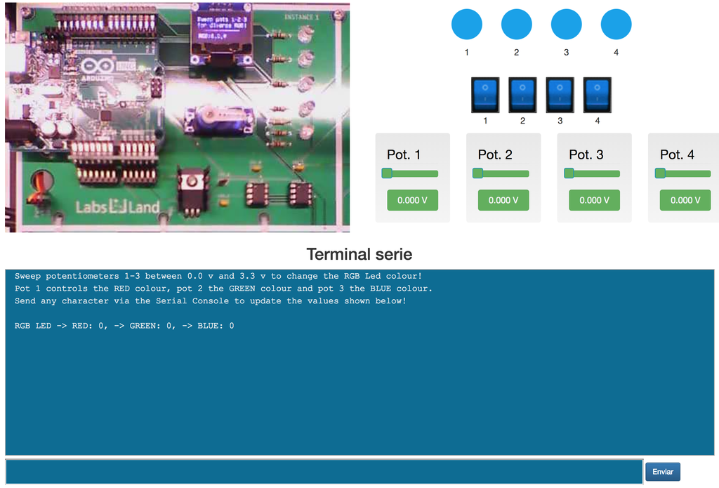
With this laboratory, you can program a real Arduino Uno board. It also includes several input and output peripherals, similar to those that are often included in Arduino starter kits.
Those peripherals include LEDs, switches, buttons, an OLED display, a servo motor, etc.
Arduino robot (code)
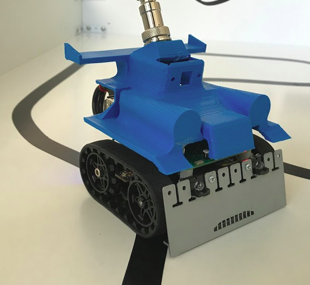
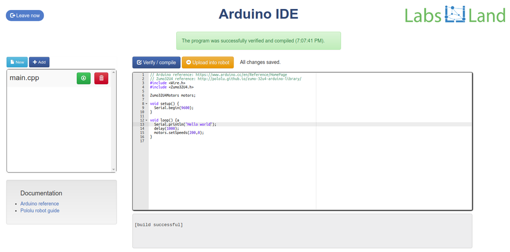
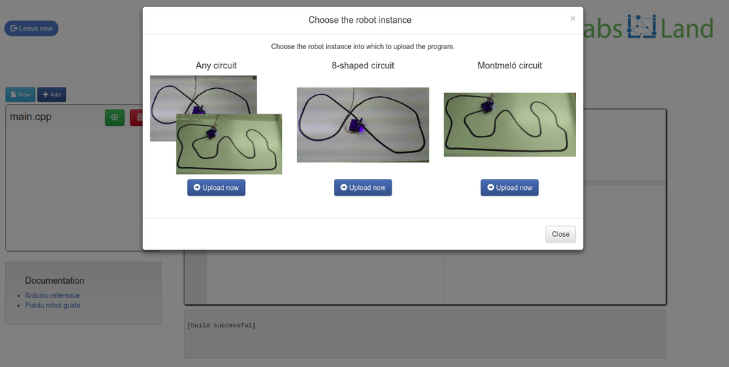
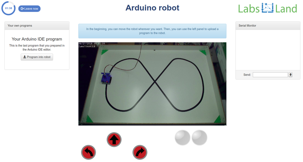
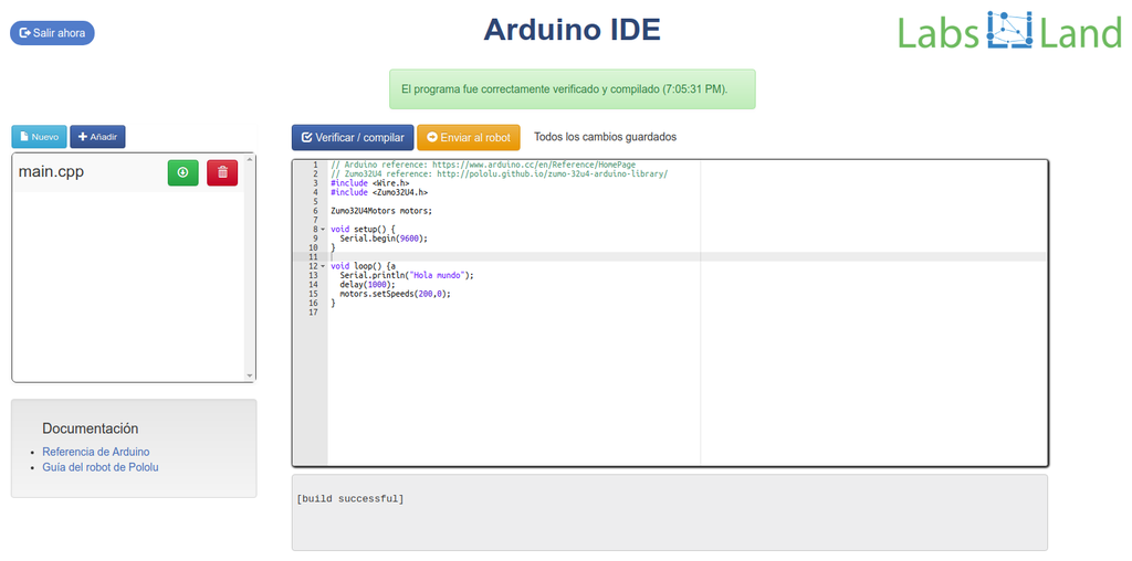
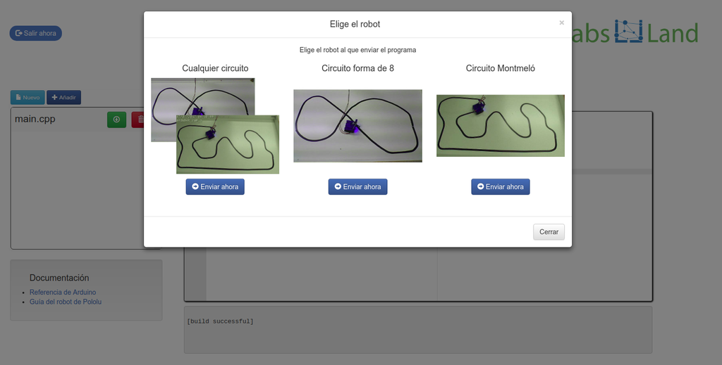
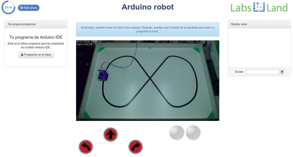
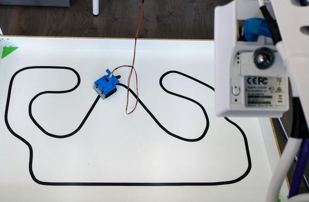
Arduino Robot laboratory lets you carry out experiments with a real robot. Define the robot's logic through programming the Arduno directly, and then upload your program into the robot to see its behaviour through a web camera. You can make your robot avoid walls, compete in line-following races, or any other type of exercise. If you prefer to use a scratch-like visual programming language, try our arduino visual robot laboratory!
Arduino robot (visual)
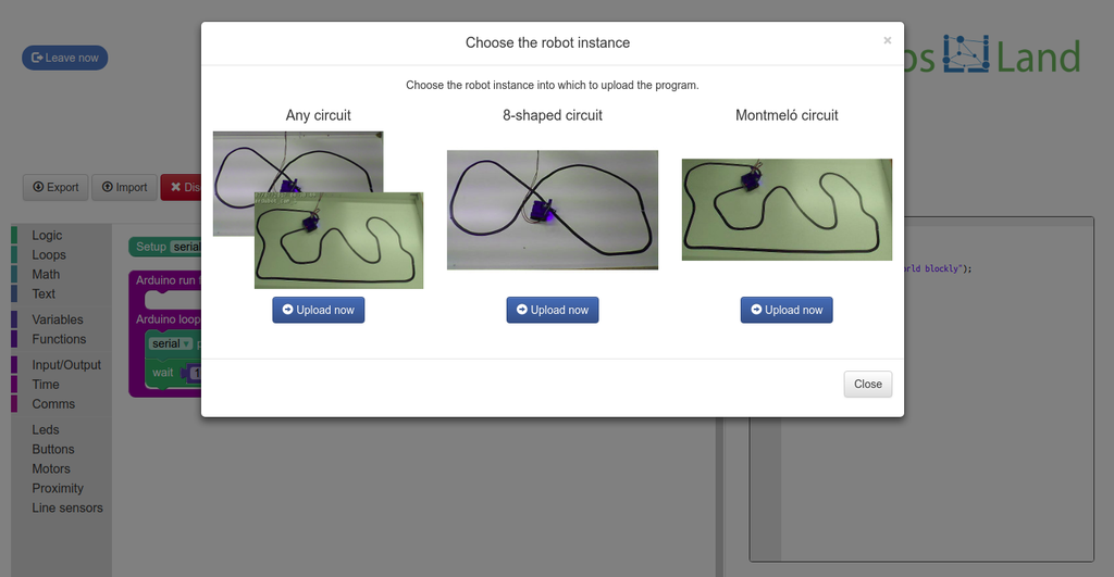
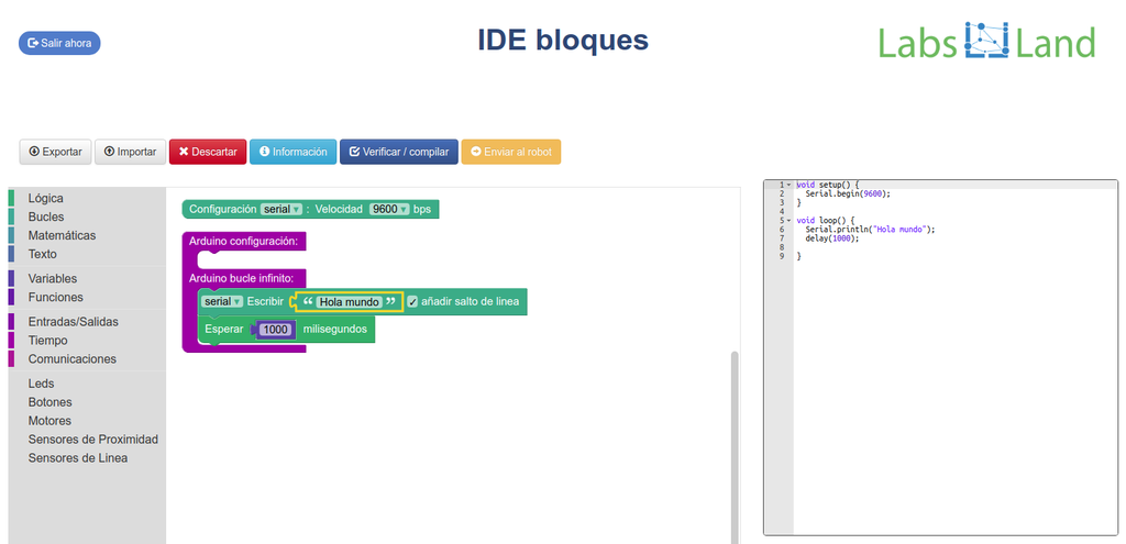
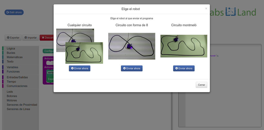
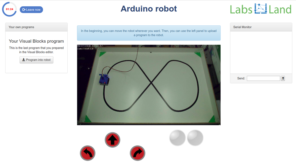
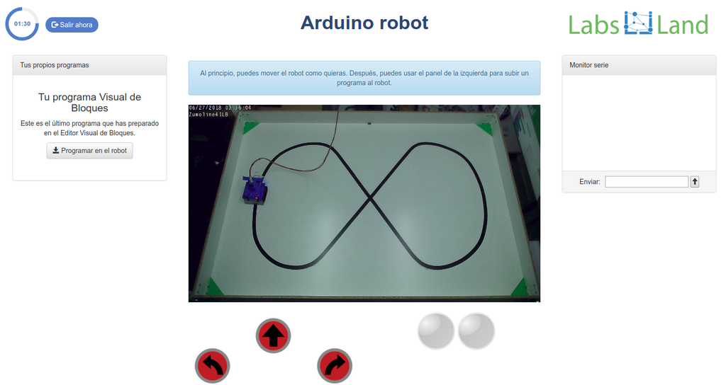
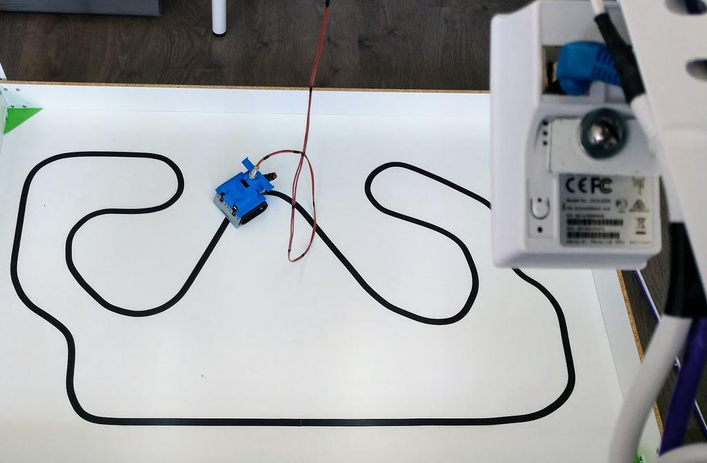
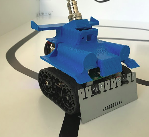
Arduino Robot laboratory lets you carry out experiments with a real robot. Define the robot's logic through a blocks-based language (Blockly), and then upload your program into the robot to see its behaviour through a web camera. You can make your robot avoid walls, compete in line-following races, or any other type of exercise. If you prefer to learn using code, you can with the code version.

ATmega328p (Assembly)
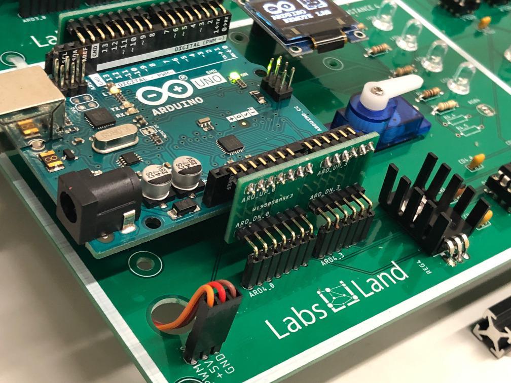
Use an online IDE to program ATMEL's ATmega328p microncontroller using assembly language. The ATmega328p is used in the Arduino UNO, which is in fact the board that you will be able to program. Various peripherals are attached, including LEDs, potentiometers and a servo motor, among others.
The hardware is shared with the Arduino Board laboratory, so activities that are possible in that one are also possible here. Additionally, it is possible to combine C source code with the assembly. Naturally, this version of the laboratory, oriented towards assembly, is more complicated to use than other versions of the Arduino lab, and it is oriented towards microprocessor, computer architecture and assembly courses.
Boole Designer
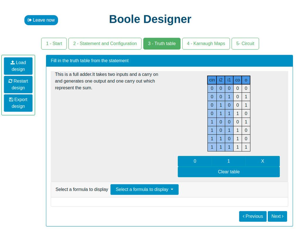
This laboratory will let you learn basic Digital Electronics.
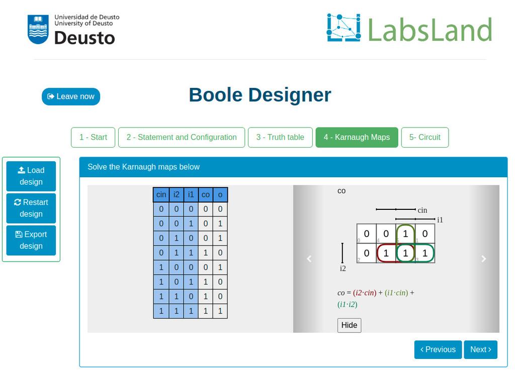
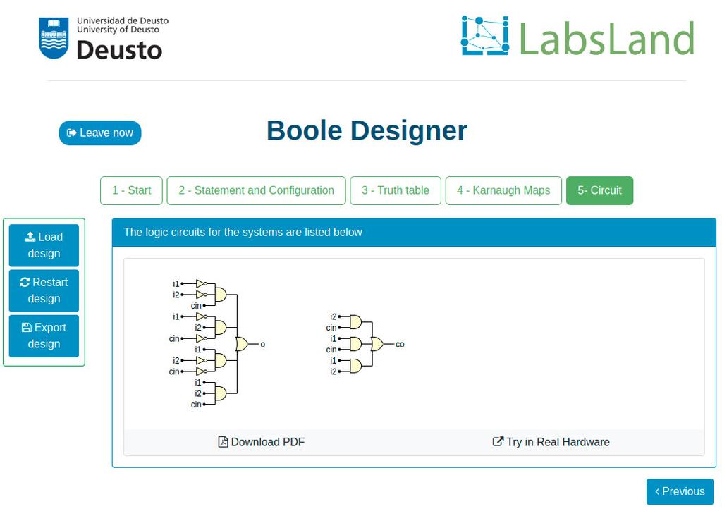
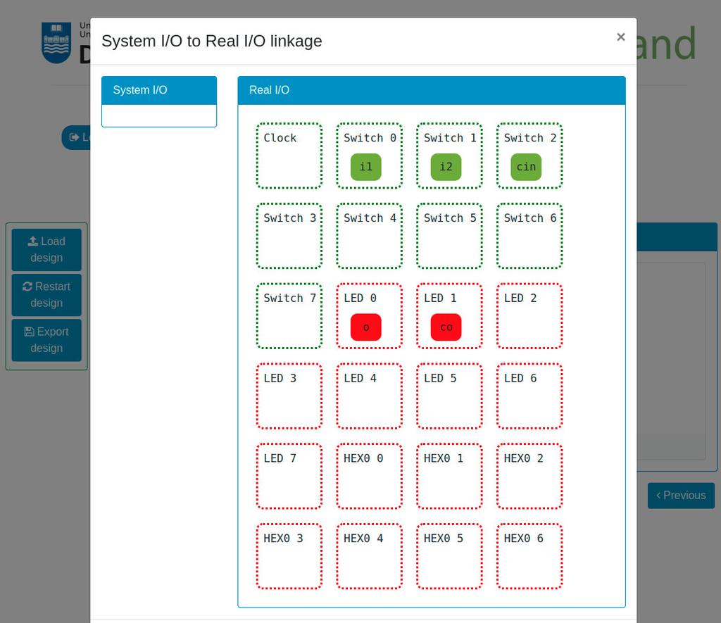
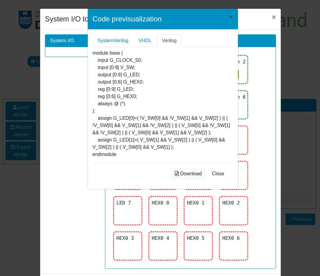
You will be able to design Combinational Systems by designing and filling a truth table, use Boolean Algebra, create Karnaugh–Veitch (KV or VK) maps, and try the systems that you create in real remote hardware (Intel FPGAs).

Digital Trainer
Summary
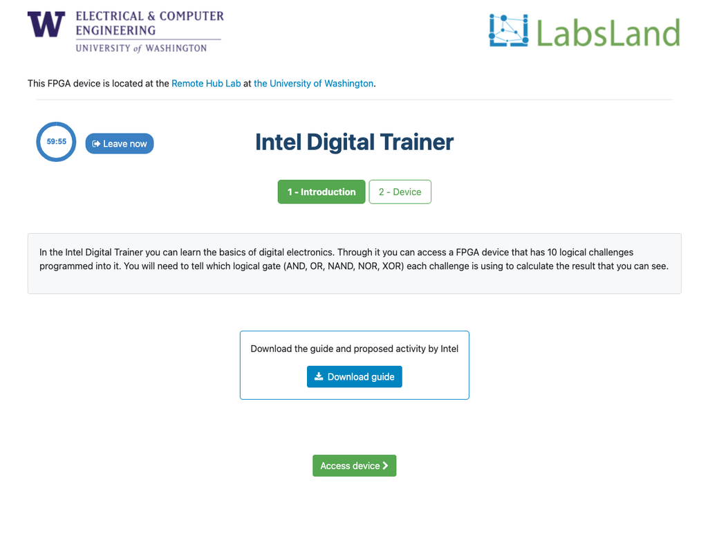
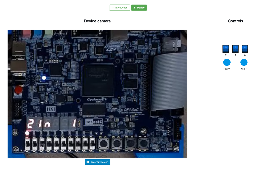
The Digital Trainer laboratory is designed towards students that are starting with digital logic, truth tables and Boole's Algebra.
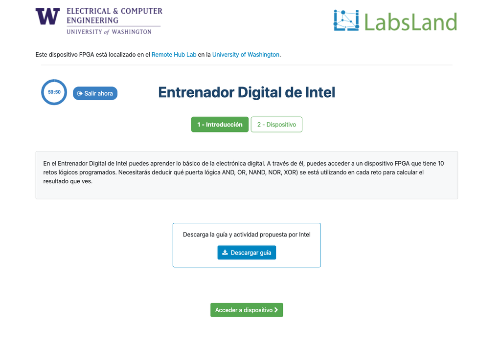
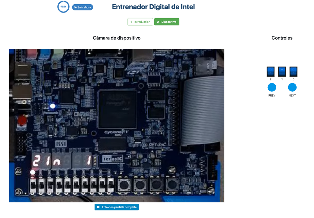
During the activity, the student sees an Intel FPGA that implements a series of simple truth tables. The student can interact with the FPGA devices to vary the inputs to the system through switches, and observe the outputs through LEDs. The challenge is to determine which logical operator the FPGA implements in each case (e.g. AND, NAND...).
Further details
The activity is designed to be relatively simple and straightforward, but at the same time to be engaging for the students. It is designed in a game-like style, and it is based in real hardware (FPGAs). That way, it is not only useful to introduce and obtain familiarity with digital logic, but also it allows students to start seeing the future uses of that knowledge, interacting in a superficial way with FPGA devices, of the same kind that are used in industry.
Interaction with the FPGA devices does not add complexity, since students don't need to program them; they already implement a black box logic (which is precisely the point of the activity).
The laboratory is originally based in an activity that Intel Corporation frequently conducts in its seminars, both hands-on and remote, using their Intel DE1-SoC, Intel DE2-115, or other types of FPGAs.
Electronics - Hive
Summary
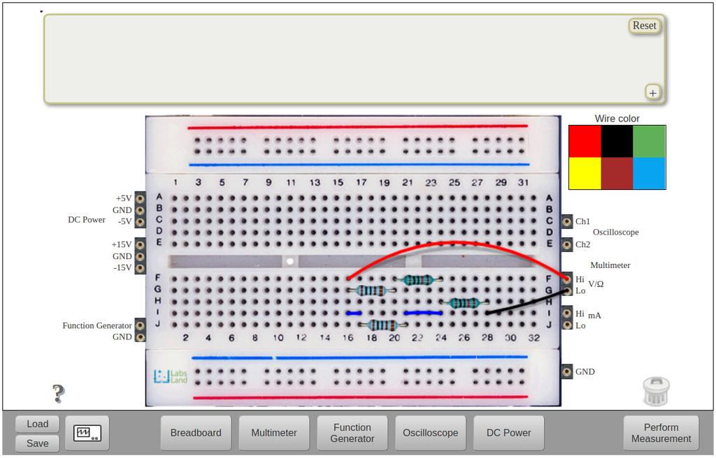
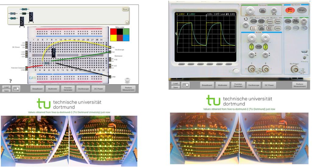
For experimentation with analog circuits. Through this tool, you will have access to your own electronics laboratory. Using its interactive interface, you can use a prototyping board to connect components and wires. You can also connect and configure a function generator and a power supply. Once the circuit is designed, you can also take measurements using the multimeter or the oscilloscope. Both the circuits and the measurements are built and taken in reality: this is not a simulation. A relay-based system connects the components as you have defined them, resulting in real signals and measurements. Useful for activities in analog electronics such as Ohm's law, Kirchoff's law, component characterization, learning about instrumentation, types of circuits, etc.
Use and Instruments
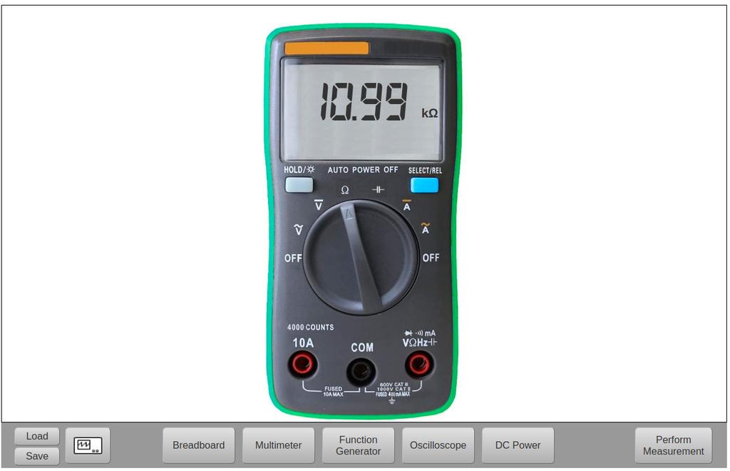
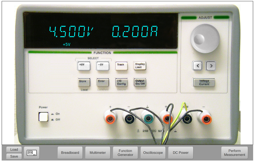
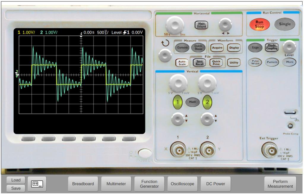
The LabsLand Electronics Lab is very powerful and is based on an interactive interface with a virtual appearance. Like in a traditional analog electronics lab, the student has access and control over a series of instruments, which are the following: prototyping board, function generator, power supply, multimeter, oscilloscope. They also have access to a component tray, which they can incorporate into their circuit.
The main element is the prototyping board. Students usually start by creating their circuit here. To create a circuit, components will be dragged from the tray (at the top of the screen) to the prototyping board, and they will be connected using wires, accessible through the top-right toolbar. The interface is very interactive, allowing you to add, move, and remove components and wires freely.
The system also allows you to load and save already designed circuits. This feature will allow you to use complex circuits as a starting point if the activity has been designed that way; or to save circuits either to keep them or to submit them at the end of an activity.
From the prototyping board, you can see several connectors on the sides, which connect the circuit precisely with the rest of the instruments. The labels on these connectors are quite descriptive, but for example, the connectors on the top left, grouped as "DC Power", where it says +5V, GND, -5V, connect the circuit to the power supply.
To observe and configure an instrument, just select it from the bottom menu. For example, by clicking on "DC Power" we access the power supply. We can act on most of its controls, and this will have a direct effect on the circuit and the measurements (assuming we have connected the circuit correctly).
Once we have designed and built the circuit correctly, and configured the instruments, to take a measurement we will press the "Perform measurement" button at the bottom right. If the circuit is correctly designed, after a short lapse of time, we will see the result of the measurement in the instruments. If we had made a mistake or if the circuit was not possible to build either for safety reasons or because it is not supported; we would see an error message.
When taking a measurement of a circuit, we will see under the interface two real-time photographs of the equipment at the moment it takes the measurement. During the lapse of time in which it is taken, the circuit is physically configured using relays. Its status can sometimes be observed through the indicator LEDs.
Circuit Catalog
The key feature of LabsLand's Electronics Lab is that it's not a simulation: the circuits are genuinely constructed using relays, all the components incorporated into the circuits (resistors, diodes, capacitors...) are real, and the measurements are taken using real instruments. This makes it an extremely realistic and powerful lab, but at the same time, it involves certain inevitable limitations.
To begin with, the lab must support (physically incorporate) the specific component to be used. You can see which components are incorporated in the component tray. Furthermore, if you want to use more than one of the same type of component, the system must have an adequate number. In addition, for safety, the system is designed not to allow any type of interconnection. Short circuits or circuits that would exceed the power supported by the components, for example, cannot be constructed. Circuits that have not been endorsed for safety also cannot be built.
Because of this, to be able to design classroom activities and to use the Electronics Lab didactically in practice, we provide and recommend using the Circuit Catalog that we supply. The LabsLand Circuit Catalog lists a large set of circuits that we guarantee can be constructed and used safely, and that are usually useful in the various courses for which the Electronics Lab is used.
By designing class activities around circuits from the catalog, we will avoid the potential problem of an arbitrary circuit not being supported, either due to safety issues, component availability, or simply because it cannot be verified that it is valid to build it.
You can access the catalog through this link: https://labsland.com/pub/docs/experiments/hive/en/index.html and it is also listed in the contents section.
The catalog includes sections with circuits for:
- Resistors
- Diodes
- RC Circuits
- RLC Circuits
- Operational Amplifiers
- Transistors
We are continuously extending the catalog. If you are interested in a type of circuit that you believe could be useful, do not hesitate to contact us. Although we cannot guarantee to add it, we can analyze it and possibly incorporate it in future revisions.
Internal Operation
The LabsLand Electronics Laboratory is composed of several "Hives" distributed in different institutions around the planet, working as a "cluster" to provide circuits and measurements to users.
When designing a circuit, the circuit is not physically constructed, and measurements are not taken until the Take Measurement button is pressed. At that moment, one of the distributed nodes is assigned, which instantly constructs the circuit, takes the necessary measurements, and returns the result. The specific node that has taken a measurement can be observed in the interface, through the two real-time photographs. Each measurement can be directed to a different node: this is why you will occasionally see the image and provider of the last measure varies frequently if several are taken.
Internally, each node is a box that contains several instruments and several boards designed by LabsLand with relays and the components that will form the circuit. The "Hive Node Reference Documentation" document explains in detail the internal operation of the nodes, as well as the purpose of each type of internal board.
The nodes are designed so that the institution hosting them can add new circuits if they wish and customize them. This is also detailed in the manual.
Equipment
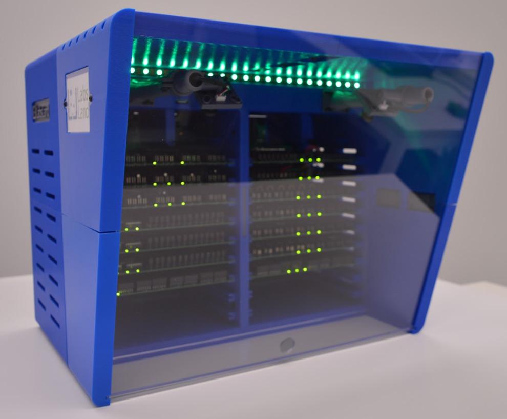
The equipment for this lab (i.e., the previously mentioned nodes) has been designed by LabsLand and is available for sale to be deployed in institutions. Institutions, by purchasing and deploying the equipment in their own facilities, obtain various benefits; among them, the ability to conduct research using them, and the ability to create and customize circuits.
For information on how to purchase the hardware, you can visit our page: https://labsland.com/en/hardware
Application in Secondary and University Education
The LabsLand Electronics Laboratory is an exceptionally valuable educational resource for both secondary and university education.
The lab provides a safe and interactive platform to explore the fundamentals of analog electronics. Students can learn about basic concepts, such as Ohm's Law and Kirchoff's Law, through experimentation with real circuits, something that would typically be limited or even out of their reach. They can also gain hands-on experience with lab instruments, such as oscilloscopes and multimeters, which are essential in the field of electrical and electronic engineering.
The lab can be used to reinforce and expand concepts introduced in electronics classes and experiment with more complex components, such as operational amplifiers and transistors, and design their own circuits for analysis and simulations.
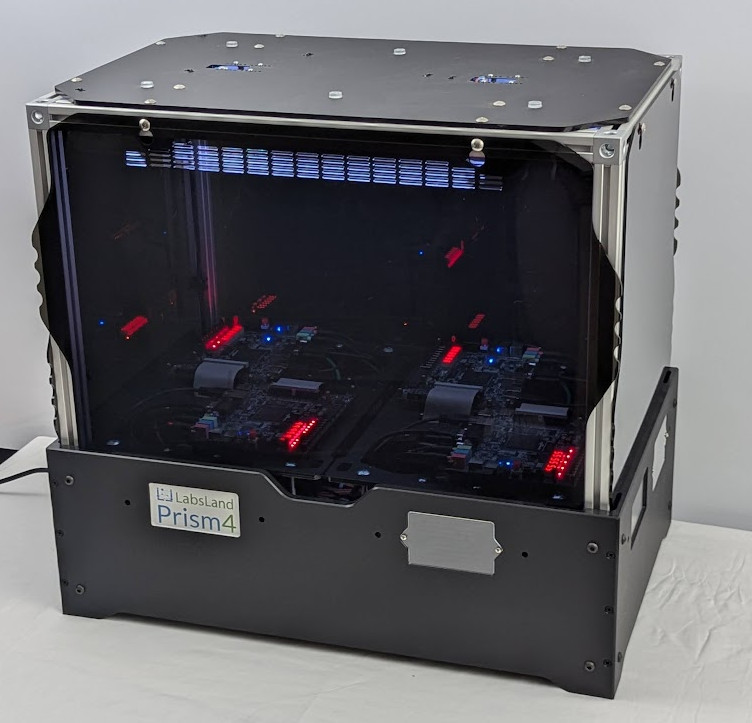
FPGA Laboratory
Learn Hardware design with real FPGAs!
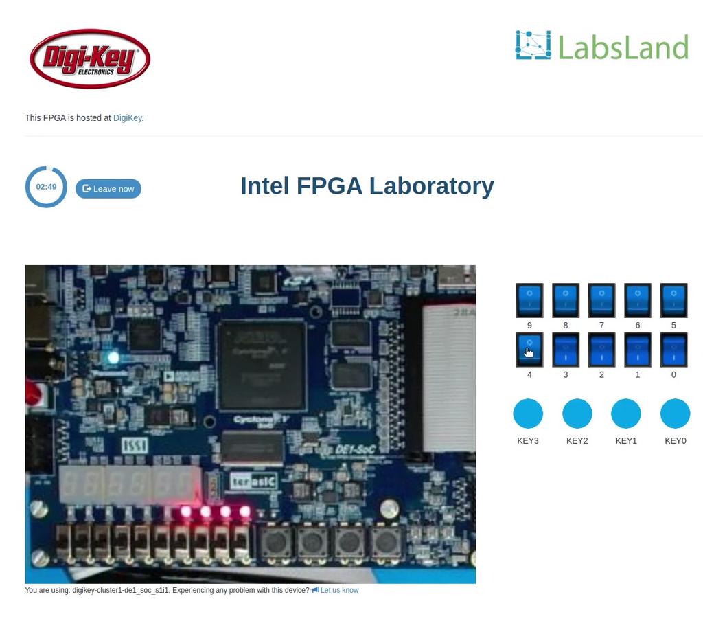
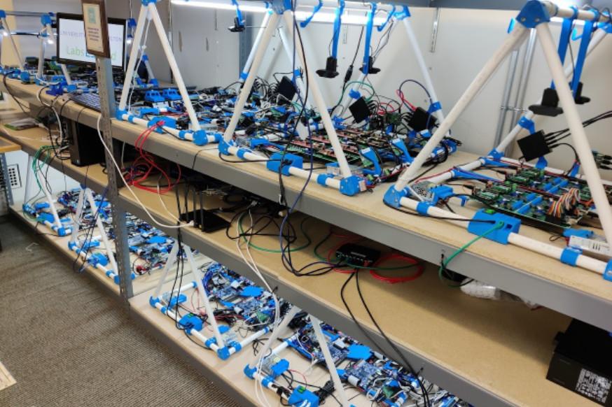
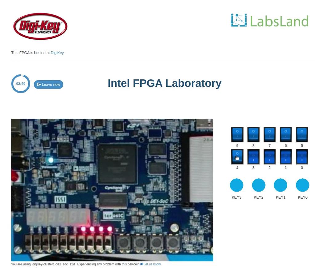
In this laboratory, you can learn how to program using two Hardware Design Languages: VHDL or Verilog, and test your code in one of our multiple boards available. Every FPGA has a set of components already place, such as 10 LEDs, 6 7-segment displays or multiple clocks. In addition, you will have access to 10 virtual switches and 4 virtual buttons that you can use in your design and that you will see when interacting with the real hardware.
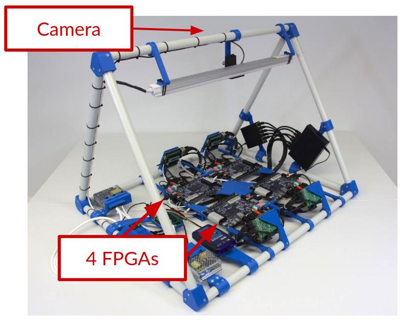
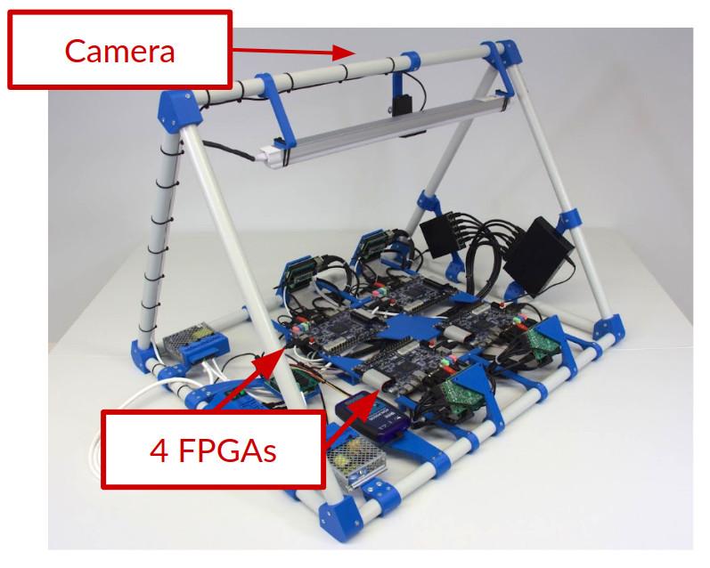
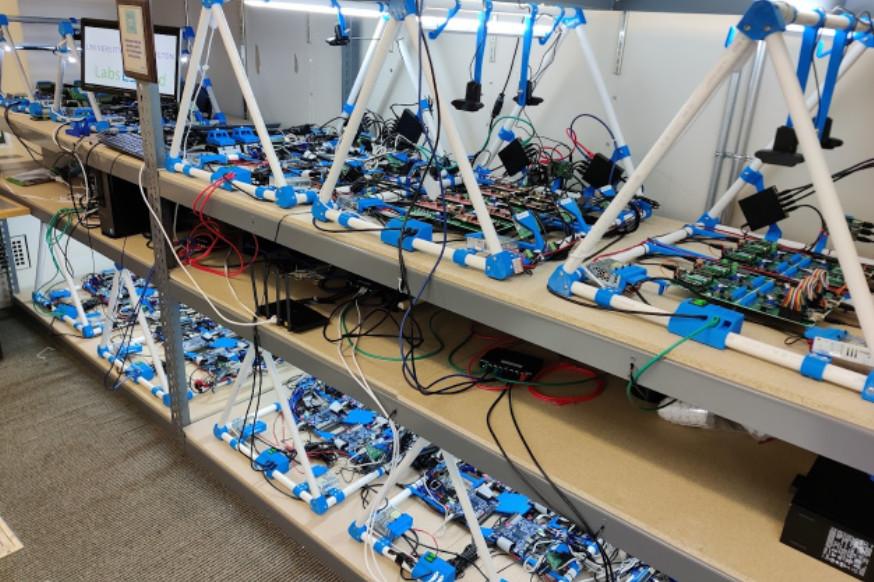
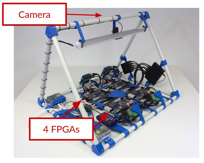
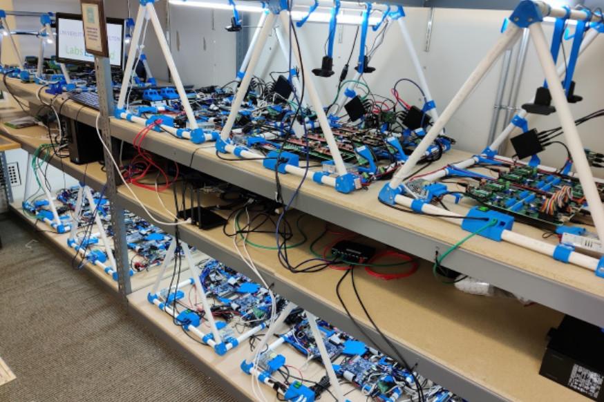
Whenever you synthesize your code, you will be assigned to a particular board (such as Terasic DE2-115 or Terasic DE1-SoC or others), and you will be able to send your code to one of the available boards and to turn on and off the switches or press the buttons and see how your design behaves. The boards are located in different universities, as you will see when using each board.
In this laboratory, you do not need any software or hardware installed in your computer, tablet or phone.
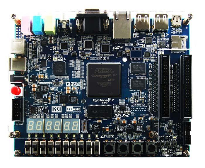
DE1-SoC
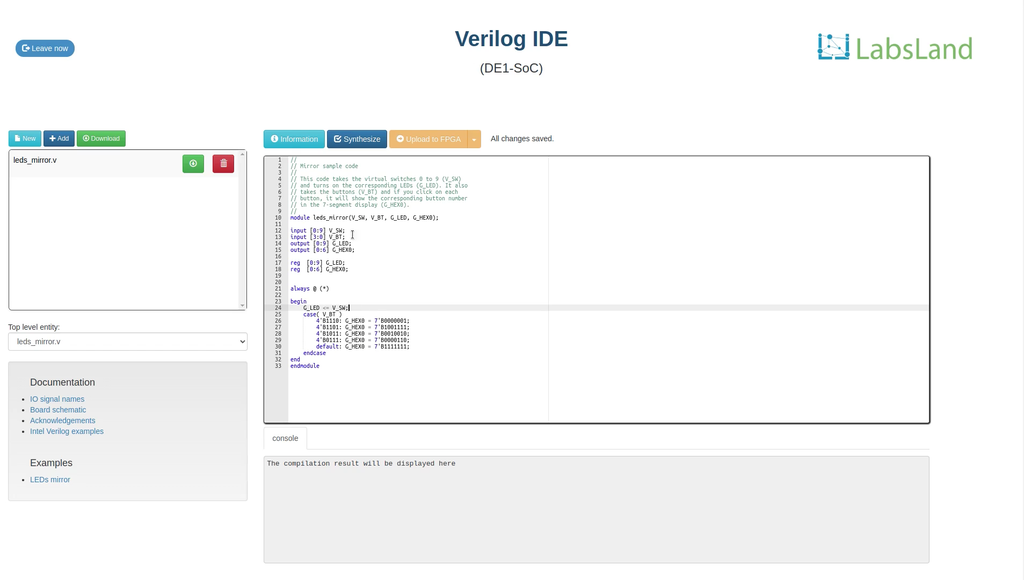
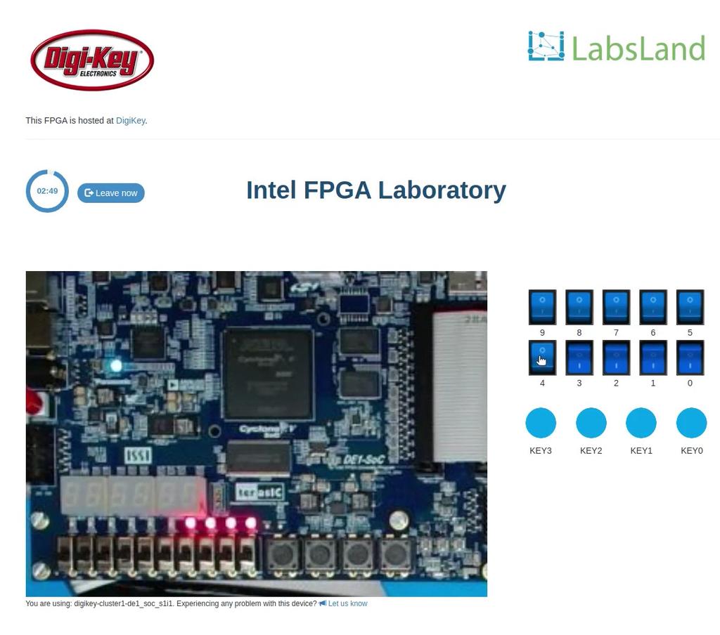
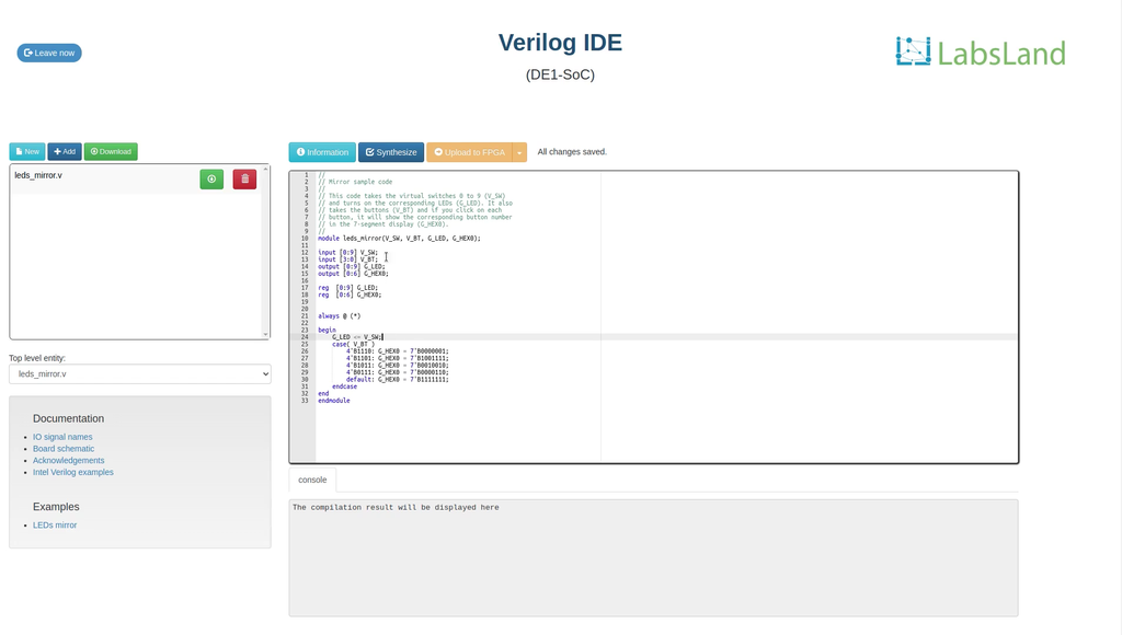
Write and compile your design in the browser, then test it on a real DE1-SoC. Observe the LEDs and seven-segment displays through the live camera and interact using the virtual switches and buttons.
To use UART, choose Standard in the interface selector and enable the UART serial terminal before entering. UART sessions use compatible boards.
DE1-SoC (binary upload)
Create and compile your FPGA design in Quartus, then upload the .sof file here. Choose the standard interface for direct access, or select an interface before entering to use other available controls and simulations.
To use UART, choose Standard in the interface selector and enable the UART serial terminal before entering. UART sessions use compatible boards.
STM32 Nucleo (C)
Summary
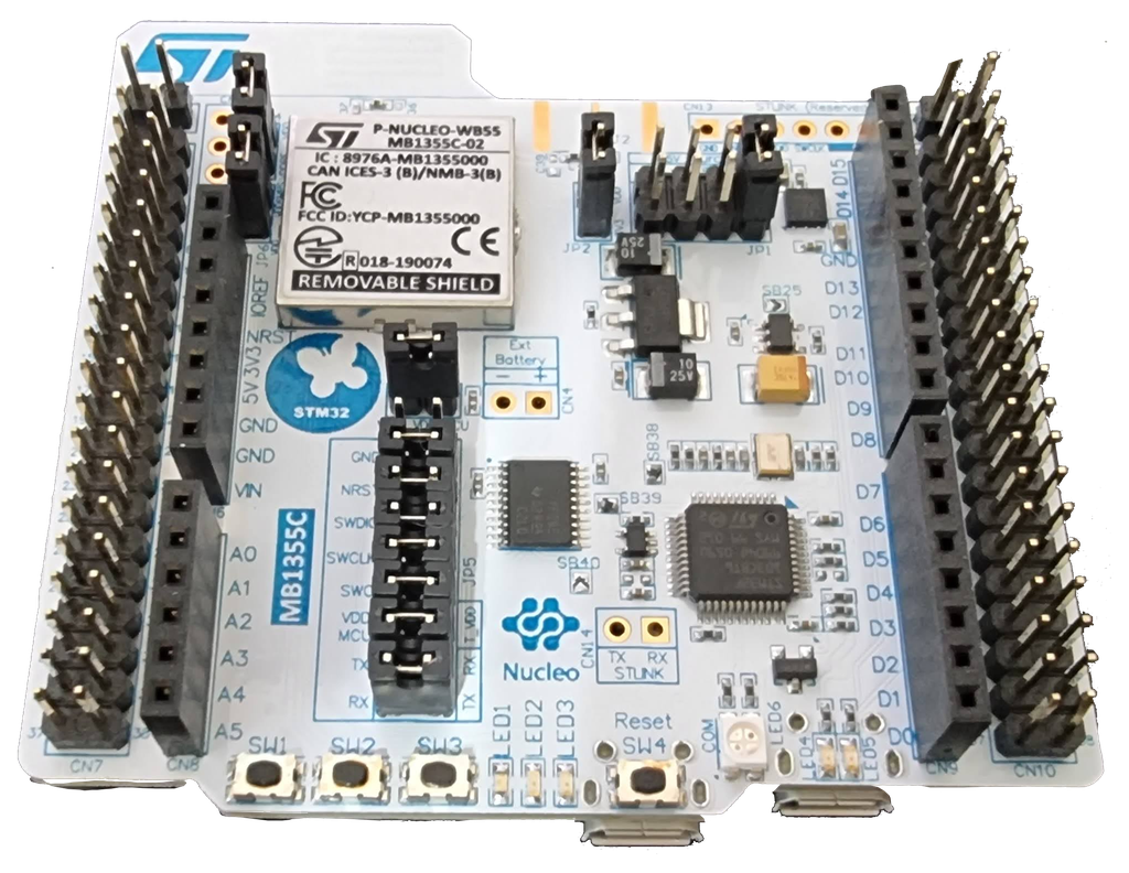
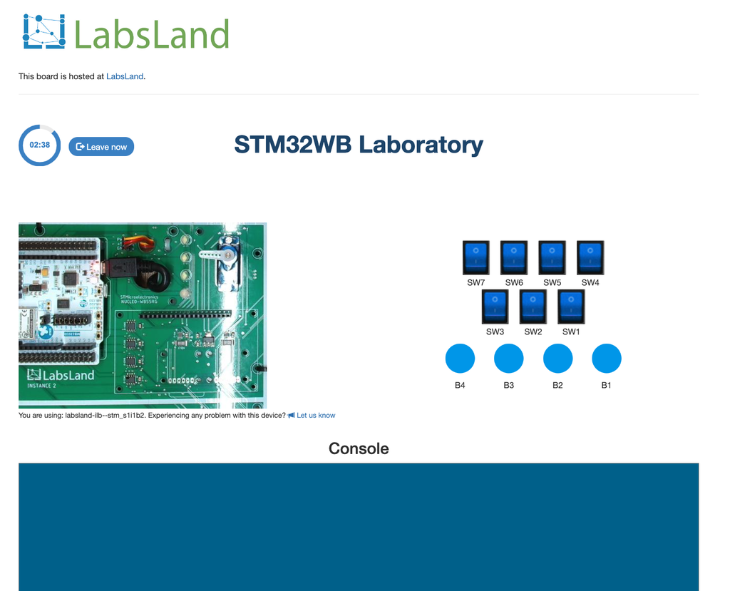
The STM32 lab allows users to program and control an ST WB55RG Nucleo board remotely. In this version of the laboratory, it is programmed using a fully web-based C/C++ online IDE. It includes various input and output peripherals, such as switches, buttons, potentiometers, and sensors, as well as an LCD screen and a servo motor. The laboratory can be used to study low-energy consumption modes. It is suitable for use in courses on embedded systems, microcontroller programming, the Internet of Things (IoT), etc.
Laboratory Hardware and Peripherals
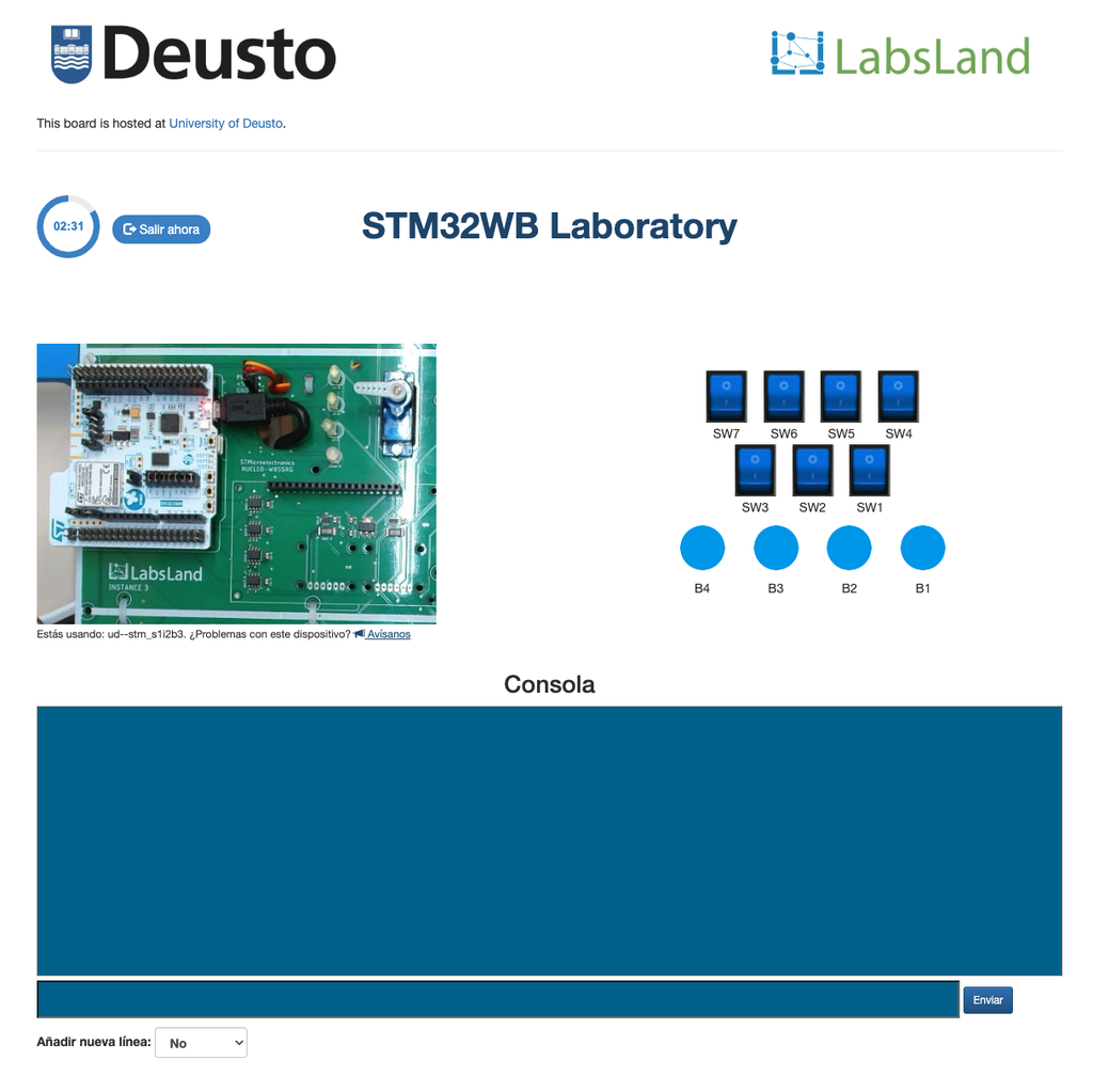
The STM32 remote laboratory by LabsLand allows users to program and control an ST Nucleo WB55RG board and various input and output peripherals, such as LEDs, an RGB LED, switches, an OLED display, and a servo motor. The laboratory also supports a range of low-power modes, including Sleep, Low-power run, Low-power sleep, Stop 0, Stop 1, Stop 2, Standby, and Shutdown. These modes can be used to study the impact of energy consumption on the performance and functionality of the STM32 board.
The online IDE
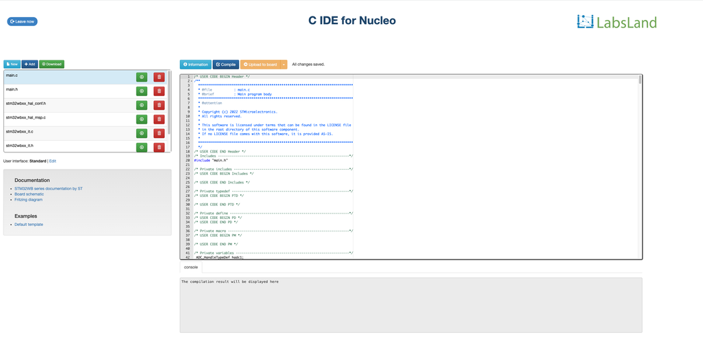
This laboratory is used through an online Integrated Development Environment (IDE) for programming the STM32 board using C/C++. This IDE, developed by LabsLand, is fully web-based and easy to use, making it suitable and effective for educational purposes. With the online IDE, students can write, compile, and upload code to the STM32 board from any computer with an internet connection. The online IDE also includes a range of features and tools.
The starting code
In traditional workflows, students using the STM32 remote laboratory by LabsLand might begin by using STM32CubeMX to generate a basic project that is compatible with the hardware and their project. To facilitate this process, LabsLand has pre-generated such a project and made it available to users as a starting point. This project is designed to be directly compatible with the hardware and serves as a good general starting point for educational purposes.
The STM32 remote laboratory relies internally on this template project, which can be downloaded by users to examine how it is configured. Users who wish to modify the template or generate their own project using STM32CubeMX can do so. In this case, they may prefer to use the alternative version of the laboratory that does not include an online IDE. That alternative version allows users to program the STM32 board using standard vendor or industry toolchains and upload a binary compiled file to the laboratory.
Courses & Applications
The STM32 remote laboratory by LabsLand is a versatile platform that can be applied to a wide range of courses, including:
- Introduction to microcontrollers
- Internet of Things (IoT)
- Low-power computing
- Sensor interfacing
- Embedded Systems
- Computer Architecture
These courses may involve programming the STM32 board, interfacing with various sensors and peripherals, and studying the principles of microcontroller-based systems and IoT. The STM32 remote lab provides the necessary hardware and software tools for hands-on learning and experimentation in these areas.
Other versions of this laboratory
In this version of the laboratory users program the boards using LabsLand's online C/C++ IDE, an easy-to-use IDE with a shallow learning cuve designed for educational use.
An alternative version of the lab is available ("STM32 Nucleo - No IDE") that is designed to be used with any toolchain, including industry-standard toolchains, offline IDEs or fully-fledged online IDEs such as Mbed's. In this alternative version, users upload directly compiled binary files to program the board.
The REMOCLEC project
The development of this laboratory is conducted as part of the REMOCLEC project. The REMOCLEC consortium, led by LabsLand, is also formed by the University of Deusto and Plegma Labs. REMOCLEC is funded by the Smart4All European project, which is funded by the European Union’s Horizon 2020 research and innovation programme.

STM32 Nucleo (No IDE)
Summary
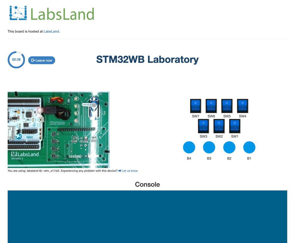
The STM32 lab allows users to program and control an ST WB55RG Nucleo board remotely. In this version of the laboratory, users can upload a compiled binary file to be programmed into the board, so they can use any kind of toolchain, including industry standard offline tools. The lab includes various input and output peripherals, such as switches, buttons, potentiometers, and sensors, as well as an LCD screen and a servo motor. It can be used to study low-energy consumption modes. It is suitable for use in courses on embedded systems, microcontroller programming, the Internet of Things (IoT), etc.
Laboratory Hardware and Peripherals
The STM32 remote laboratory by LabsLand allows users to program and control an ST Nucleo WB55RG board and various input and output peripherals, such as LEDs, an RGB LED, switches, an OLED display, and a servo motor. The laboratory also supports a range of low-power modes, including Sleep, Low-power run, Low-power sleep, Stop 0, Stop 1, Stop 2, Standby, and Shutdown. These modes can be used to study the impact of energy consumption on the performance and functionality of the STM32 board.
Uploading binary files
This version of the STM32 laboratory allows users to upload compiled binary files to be programmed into the board. Various specific formats are supported, including .bin, .axf, .hex or .elf. All STM32 toolchains and IDEs will generate one of these formats, so the laboratory is compatible with any kind of workflow.
Students can leverage any of the traditional tools (e.g. STM32CubeMX) or desktop-based IDEs and toolchains (Keil, STM32CubeIDE, Eclipse with a GCC-ARM toolchain, etc).
Hardware arrangement and starting template
Students can freely use STM32CubeMXProgrammer. To facilitate this process, LabsLand has pre-generated such a project and made it available to users as a starting point. This project is designed to be directly compatible with the hardware and serves as a good general starting point. It can be modified freely.
There are also multiple guides and specifications describing how the remote hardware is connected, so students can alternatively use that information to build their own STM32CubeMX configuration from scratch.
Courses & Applications
The STM32 remote laboratory by LabsLand is a versatile platform that can be applied to a wide range of courses, including:
- Introduction to microcontrollers
- Internet of Things (IoT)
- Low-power computing
- Sensor interfacing
- Embedded Systems
- Computer Architecture
These courses may involve programming the STM32 board, interfacing with various sensors and peripherals, and studying the principles of microcontroller-based systems and IoT. The STM32 remote lab provides the necessary hardware and software tools for hands-on learning and experimentation in these areas.
Other versions of this laboratory
In this version of the laboratory ("STM32 Nucleo - No IDE") students upload a compiled binary file, so it is designed to be used with any toolchain, including industry-standard toolchains, offline IDEs or fully-fledged online IDEs such as Mbed's.
An alternative version of the laboratory exists in which users program the boards using LabsLand's online C/C++ IDE, an easy-to-use IDE with a shallow learning cuve designed for educational use. Though less powerful than this version, the online IDE allows students to get started in seconds and without needing to install any software on their devices. It is therefore suitable for introductory activities.
The REMOCLEC project
The development of this laboratory is conducted as part of the REMOCLEC project. The REMOCLEC consortium, led by LabsLand, is also formed by the University of Deusto and Plegma Labs. REMOCLEC is funded by the Smart4All European project, which is funded by the European Union’s Horizon 2020 research and innovation programme.
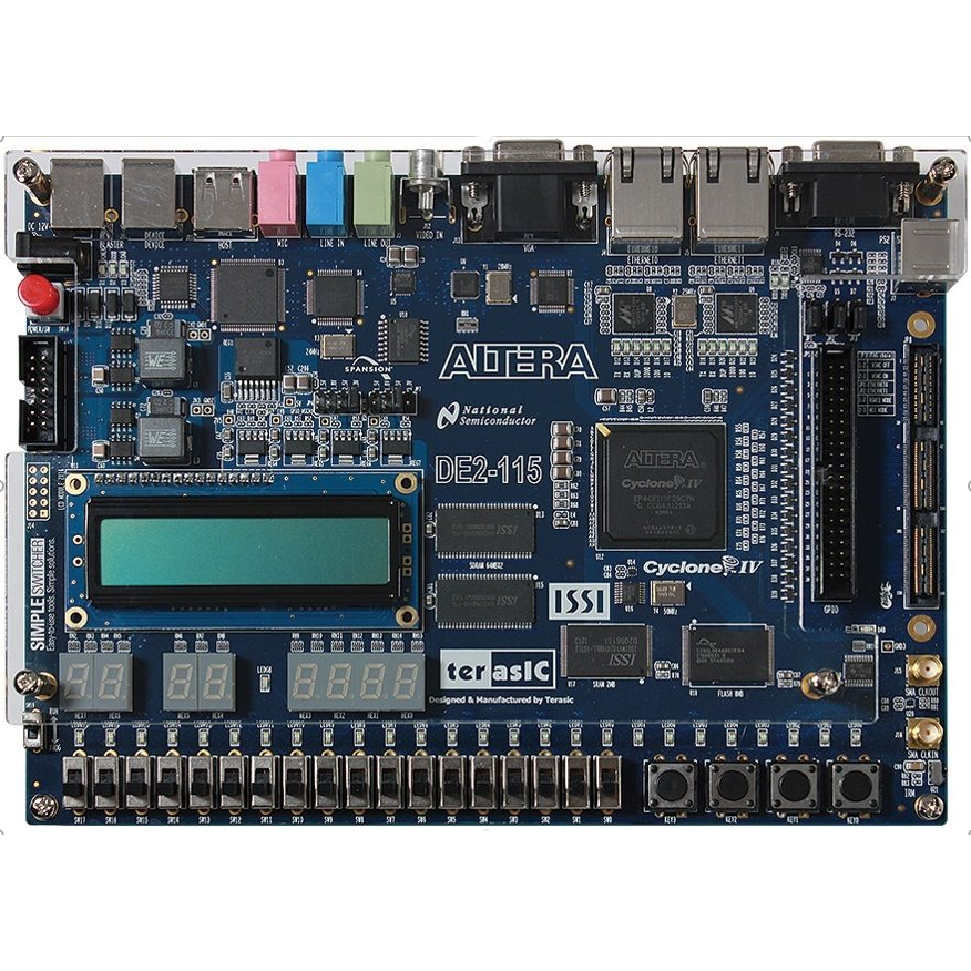
Intel DE2-115 (no IDE)
Learn Hardware design with FPGAs using Terasic DE2-115!
In this laboratory, you can learn how to program using two Hardware Design Languages: VHDL or Verilog, and test your code in a real Terasic DE2-115 FPGA. The FPGA has a set of components already place, such as LEDs, 7-segment displays or multiple clocks. In addition, you will have access to 18 virtual switches and 4 virtual buttons that you can use in your design and that you will see when interacting with the real hardware. This way, you will be able to turn on and off the switches or press the buttons and see how your design behaves. The boards are located in different universities, as you will see when using each board.
In this laboratory, you do not need any software or hardware installed in your computer, tablet or phone.