5. Using the instruments
To finish assembling the circuit, it is necessary to connect the circuit to the instruments. To do this, it must be taken into account which instruments are needed. Previously, a list has been made with the necessary instruments.
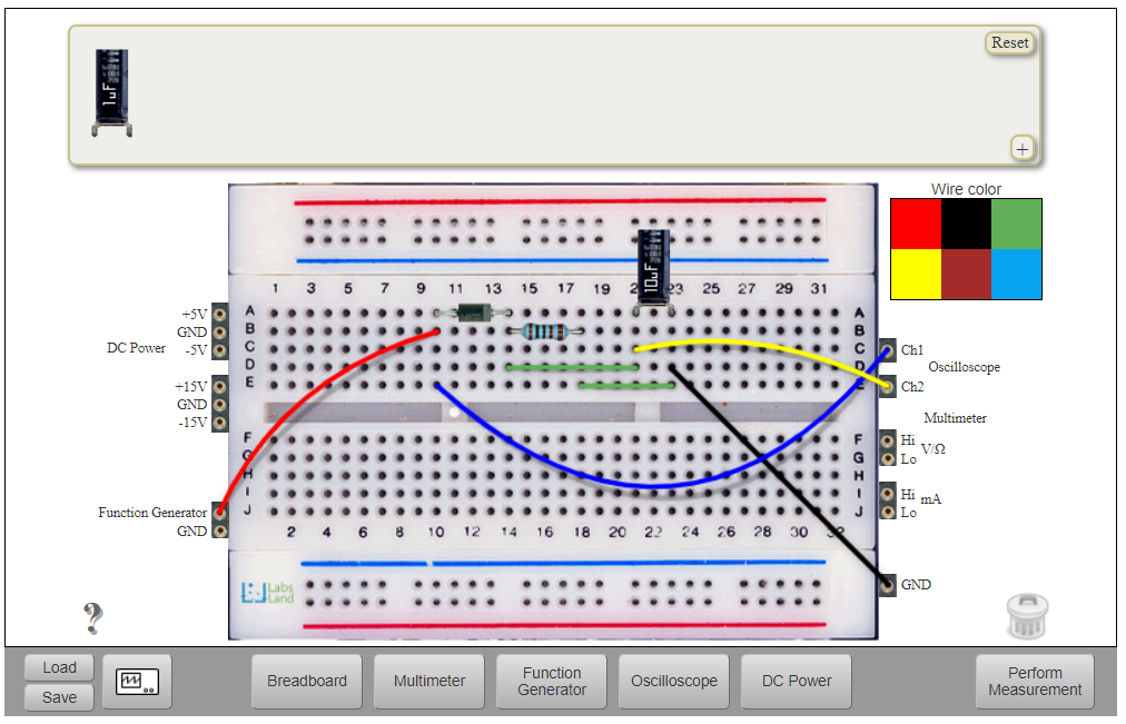
Fig. 5.1 Half-wave rectifier circuit with instruments connected.
Fig. 5.1 shows:
Red wire joins the function generator and the diode’s anode. Function generator’s ground is not required to be connected to ground because it is the same as the GND terminal at the right side.
Blue wire joins the input of the circuit with CH1 at the oscilloscope.
Yellow wire connects the output of the circuit with CH1 at the oscilloscope.
5.1. Setting up the Function generator
To set up the function generator, click on the “Function Generator” button at the Instruments area ( Fig. 4.1). After clicking it, you will see the following interactive panel.
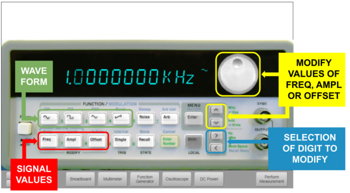
Fig. 5.1.1 Function generator.
The first step is to select the value to be modified. For example: frequency. The second step is to choose the digit to be modified. To choose the digit, Fig. 5.1.1 shows on the right a panel for that purpose. The digit being modified blinks. After having modified all the values indicated in the statement, the wave form to be used must be chosen.
The example being followed ( Fig. 4.2) has the following data:
Frequency = 100Hz.
Amplitude = 10VPP.
Offset = 0V.
Wave form = Sine.
Once the circuit has been defined and the function generator has been set up, the circuit must be executed in order to be implemented physically using the real components of the remote lab. Then, click the button in the bottom right corner labeled “Perform Measurement”. If the circuit has been set up correctly, the image of the cameras will be updated showing on which Hive the experiment has been performed and no error message should appear.
5.2. Setting up the Oscilloscope
Once the circuit is correctly implemented, signals can be shown at the oscilloscope display. Click on the “Oscilloscope” button at the Instruments area ( Fig. 4.1). After clicking it, you will see the following interactive panel.
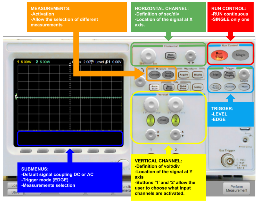
Fig. 5.2.1 Oscilloscope.
The oscilloscope Hive offers is very similar to a hands-on lab oscilloscope in appearance. It offers multiple features in order to analyze signals. Fig. 5.2.1, Fig. 5.2.2, Fig. 5.2.3, Fig. 5.2.4 and Fig. 5.2.5 show the controls of the osocilloscope.
Note: this oscilloscope does not implement the Auto Scale function in order the user has to define by him/herself the correct configuration of the instrument.
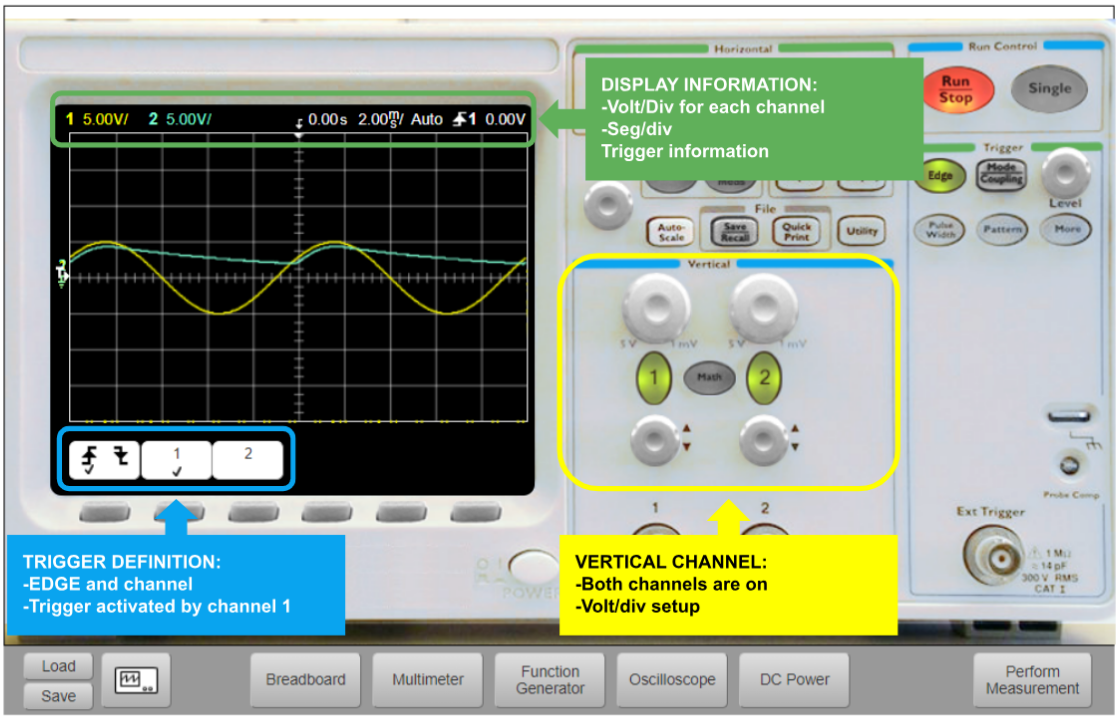
Fig. 5.2.2 Oscilloscope with half-wave rectifier signal.
Following the example, the yellow signal refers to CH1 and the blue signal to CH2 (input and output respectively).
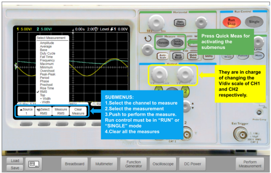
Fig. 5.2.3 Oscilloscope with possible measurements from CH1 and CH2.
In case the user wants to analyze only one of the two signals (i.e. CH1), he/she should push the ‘2’ button in order to turn off the second channel. For choosing the measurements, the “Quick Meas” button must be pressed.
Fig. 5.2.4 shows only the 1st channel and Fig. 5.2.5 shows only the 2nd channel.
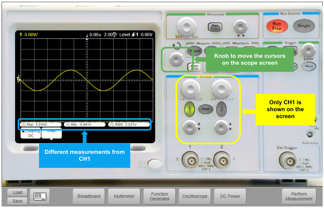
Fig. 5.2.4 Oscilloscope with measurements from CH1 only.
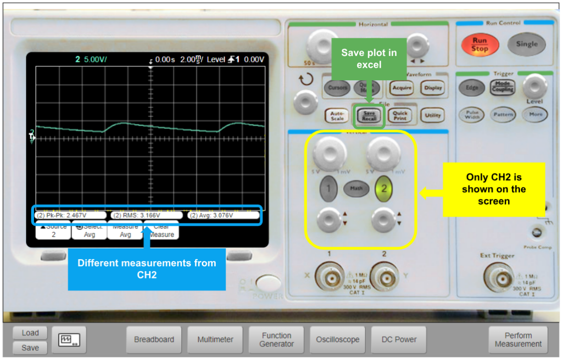
Fig. 5.2.5 Oscilloscope with measurements from CH2 only.
That is all regarding how to use the instruments. Continue in Taking measurements.
