6. Taking measurements
6.1. Setting up the Digital Multimeter
The digital multimeter available on the remote lab is the same that is commonly used in a hands-on lab. Thanks to it, user can measure resistances, capacitances, voltages and currents.
Depending on the measure to perform on the circuit, the terminals of the DMM to connect are different. Hi & Lo (V/Ω) terminals are used to measure voltages and resistances while Hi & Lo (mA) terminal are used to measure currents. Fig. 6.1.1 shows how the DMM is connected to measure the value of a resistor.
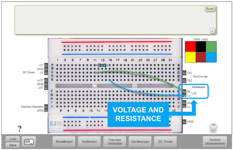
Fig. 6.1.1 Digital multimeter connection for measuring a resistor.
The DMM front panel is accessed through the “Multimeter” button at the Instruments area.
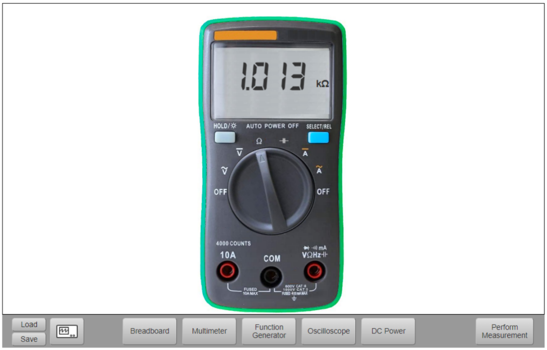
Fig. 6.1.2 Digital multimeter in ohmmeter mode.
To obtain the value of the carried out measurement, turn the central knob of the DMM and push the “Perform Measurement” button.
Current measurement is a little special because in this case the DMM must be placed on the branch where the current flows. That is, the user has to open the branch and connect there the DMM. Fig. 6.1.3 shows the three branched where the DMM can be placed to measure currents.
IMPORTANT: due to this remote lab is implemented over real components and then, circuits are reals, current measurements only can be possible before the first component in each branch.
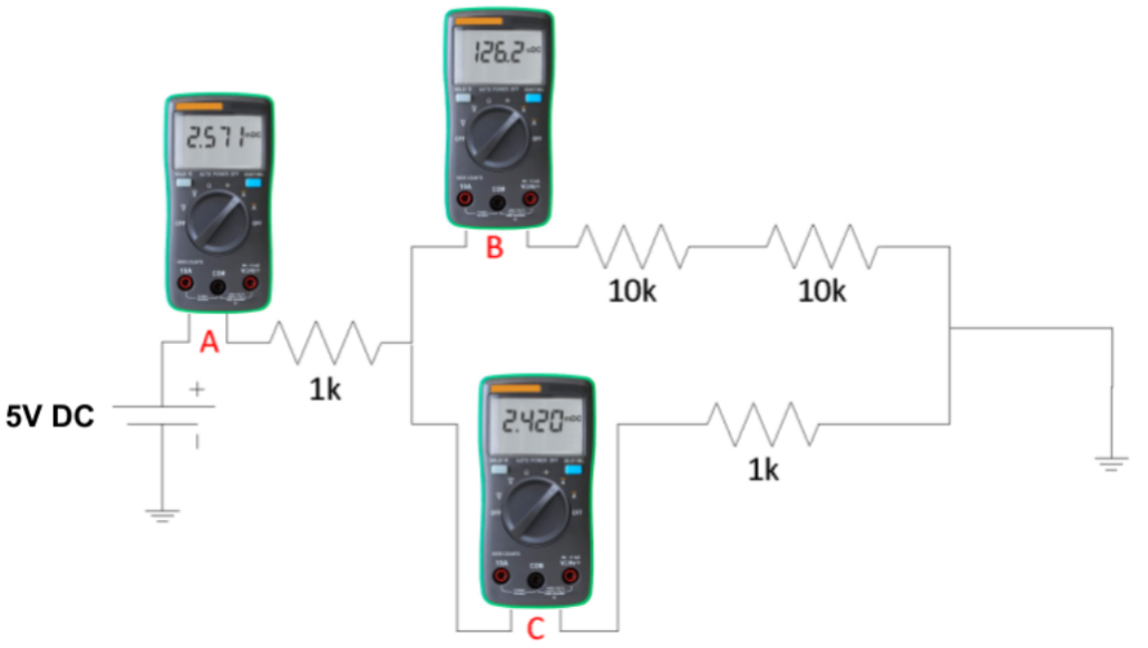
Fig. 6.1.3 Example of current measurement.
Fig. 6.1.4 shows an example where it is measured the current that flows through the hole circuit, that is, A point at Fig. 6.1.3.
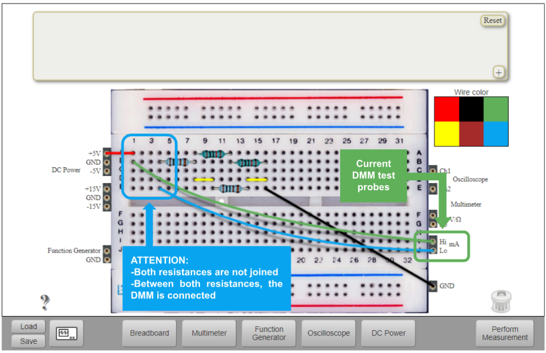
Fig. 6.1.4 Ammeter connection in the breadboard.
6.2. DC Power Supply
Power supply front panel appears after pushing “DC Power” button at Instruments area (Fig. 4.1). Voltage (+5V and -5V) values can be set up in this front panel (Fig. 6.2.1) following the same steps as in the Function Generator.
The minimum value for the +5V channel is 0.5V and the maximum value is 5V.
The minimum value for the -5V channel is -5V and the maximum value is -0.5V.
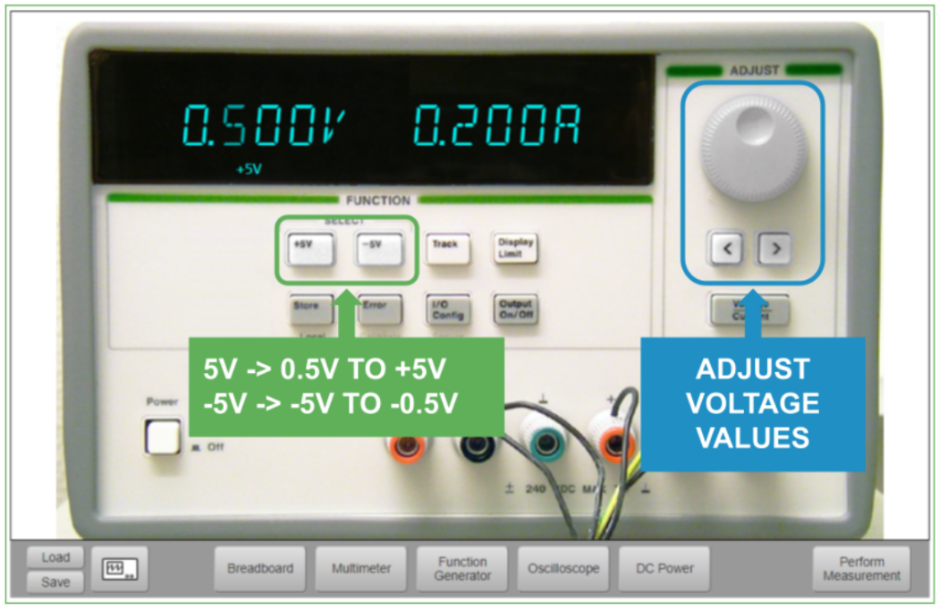
Fig. 6.2.1 DC power supply.
In case of needing +15V and/or -15V, there is also a DC non-programmable power supply. The connections can be found at the left side of the Implementation area (see Fig. 4.1).
This was the last chapter. However you also have the FAQ: Frequently Asked Cuestions.
