4. Implementing a circuit
Once all the components are selected, it is time to implement the circuit. The first thing to do is to position the components on the breadboard.
Important: the connections of the breadboard are exactly like the real ones: the holes in the same column are interconnected excep for the two rows between a red line and a blue line. In those rows, the holes in the same row are interconnected.
Then it is time to connect the components together with wires. For using a wire, first you must select the color of you choice and then click from the place you want it to start until the place you want it to end. They are completely customizable in shape and length.
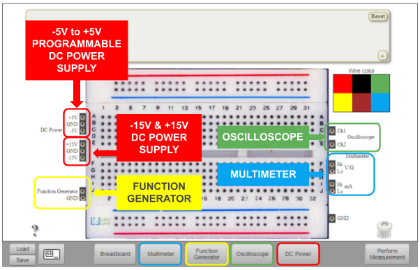
Finally, the circuit must be connected to the desired instrumentation equipment by means of cables. The instruments are placed in both sides of the breadboard. As in the figure below, the instruments that are available are the following:
Multimeter.
Function generator.
Oscilloscope.
DC power supply.

Fig. 4.1 Instruments on the breadboard.
Important: when creating a circuit you must always connect the circuit to the ground. Exceptions:
Measuring the resistance of a resistor.
Measuring the capacitance of a capacitor.
Connecting an AC signal directly to the oscilloscope.
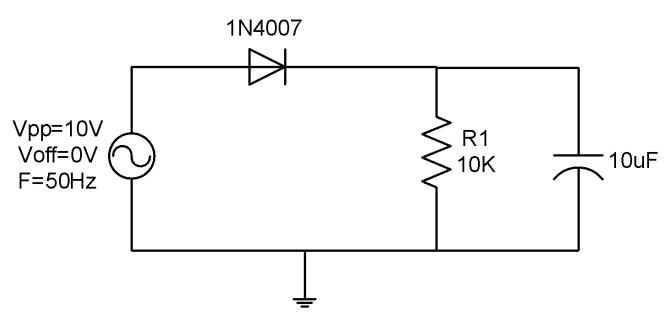
It is proposed in Fig. 4.2 as example to follow up step by step its implementation test.

Fig. 4.2 Circuit under test schematic.
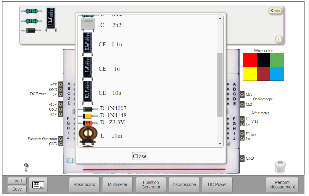
The required components and instruments to implement and test the circuit are:
10k ohms resistor.
10uF capacitor.
Function generator.
Oscilloscope.
Multimeter.

Fig. 4.3 Choosing half-wave rectifier circuit components.
Once the components are chosen, it is time to build the circuit by connecting the components as in the schematic. In order to do that, just move the components from the Components area to the Implementation area and connect them by means of cables.
Note: sometimes it is not necessary to use a wire to connect two components. If one leg of each component is in one hole of the same column they are already connected. See Fig. 4.4 to see how the resistor and the diode are connected.

Fig. 4.4 Choosing half-wave rectifier circuit components.
You may continue in Using the Instruments.
