2. User Interface
The user interface is composed of 3 parts: the user interaction zone, the visualization zone and the documentation and circuits zone.
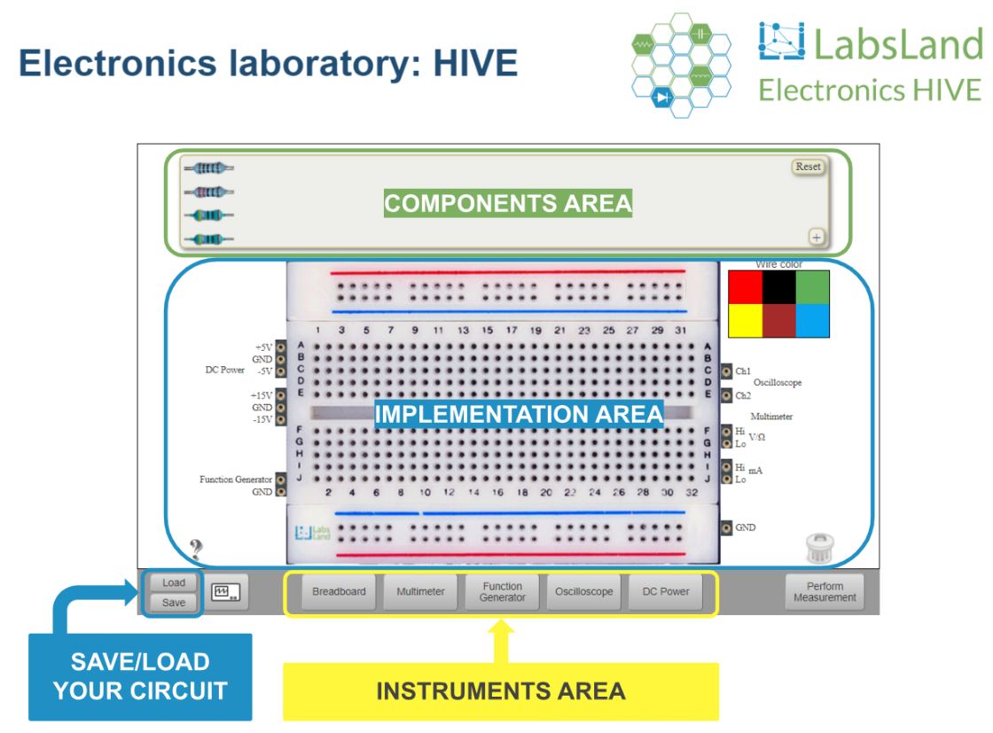
First, the interaction zone is where the users are going to make their circuits. This zone is divided into 4 parts:
Components area: allows the access to the electronic components provided by the laboratory.
Implementation area: here the desired circuits can be mounted on the breadboard.
Instruments area: this is the part of the interface where you can access the various instruments available.
Save/load your circuit area: this feature allows the user to save both online and locally a circuit he/she has made. The configuration of the instruments used is also saved. Once you have saved one circuit, you can load it once again.

Fig. 2.1 Hive user interface: interaction zone
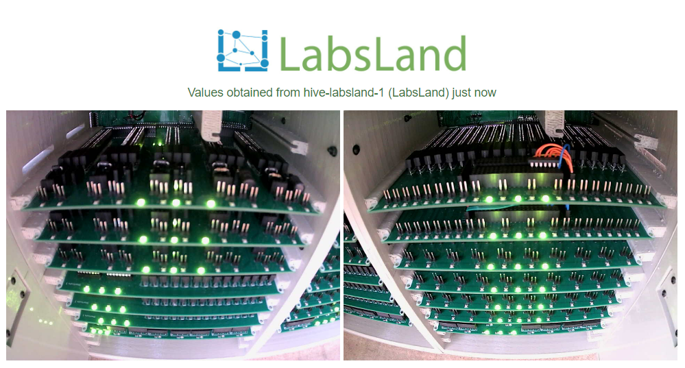
Second, the visualization zone. As this is a remote laboratory, all the measurements performed are real, no virtualization is involved. To get a more realistic and closer feeling to the experiment, the interface shows the real equipment with which the measurement has been taken at that very moment.

Fig. 2.2 Hive user interface: visualization zone
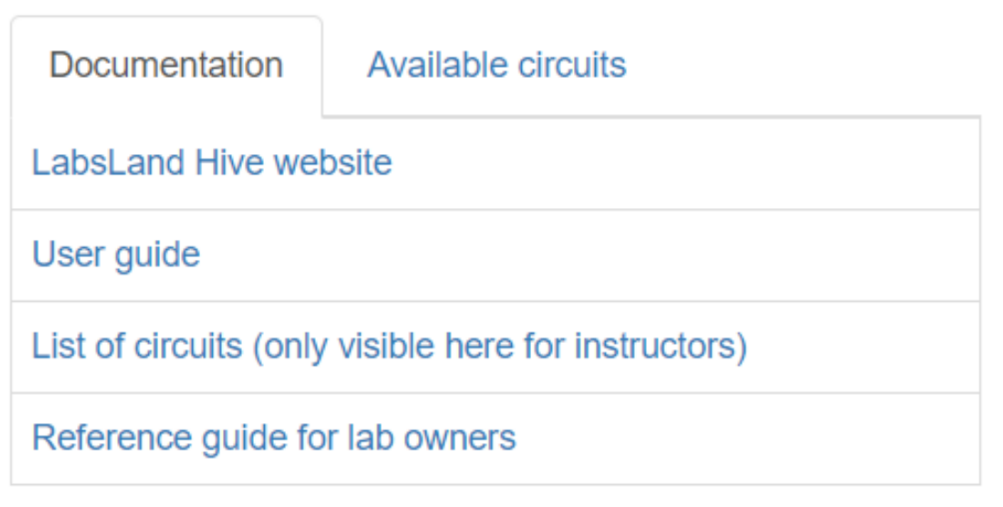
Third, documentation and circuits zone. The interface also has a feature for loading predefined available circuits. This feature allows the user to load predefined circuits that may be of interest to the user.
Finally, next to the available circuits section, you will find the laboratory documentation in case you have any doubts on how to use it.

Fig. 2.3 Hive user interface: documentation and circuits zone
You can see altogether working on the following video:
That is all in this chapter. Please continue in Manipulating components.
