Digital design · Teaching guide
A first remote FPGA assignment in Verilog: from requirement to truth table
A useful first FPGA assignment should end with more than a glowing LED. Ask students to turn a written requirement into a circuit, test every input combination and explain how their observations support their design.
This guide uses a three-input access rule on a real remote DE1-SoC FPGA. It is small enough to inspect completely, and it comes with a plausible wrong answer that passes a casual “the light turns on” check. You can use the student worksheet directly and keep the reference solution for feedback.
Set up the DE1-SoC Verilog profile
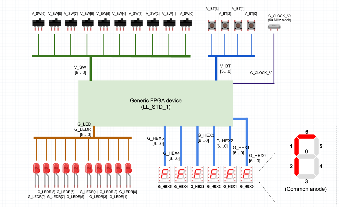
The DE1-SoC laboratory provides browser-based design tools, virtual input controls and a camera view of the physical board. For this assignment, use the DE1-SoC Verilog profile described in the first-gates Teach lesson: the file and top-level module are leds_mirror.v and leds_mirror, with SW inputs and LEDR outputs.
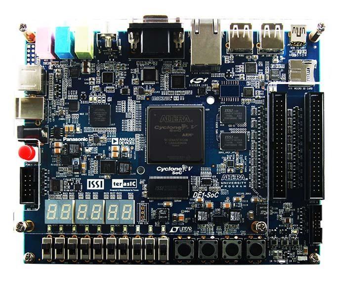
Before class, open the lab the way your students will and check the switch controls, camera view and where students will submit their work. Give students the worksheet and marking criteria before they start. If they are learning VHDL, the same requirement and truth table work with the VHDL first-gates lesson; the complete code supplied here is the Verilog version.
1. Start with a requirement students can challenge
A teaching circuit has an enable input, E, and two permission inputs, A and B. Its indicator Y must turn on only when E is on and at least one permission is on. If E is off, Y must stay off, regardless of A and B.
Map E to SW[2], A to SW[1], B to SW[0], and Y to LEDR[0]. There is no stored state and no clock: the output depends on the current inputs.
Give students ten minutes to complete the eight-row truth table before showing code. Ask them to explain why E = 0 makes four different rows share the same output. Then ask which rows show that permission alone is insufficient.
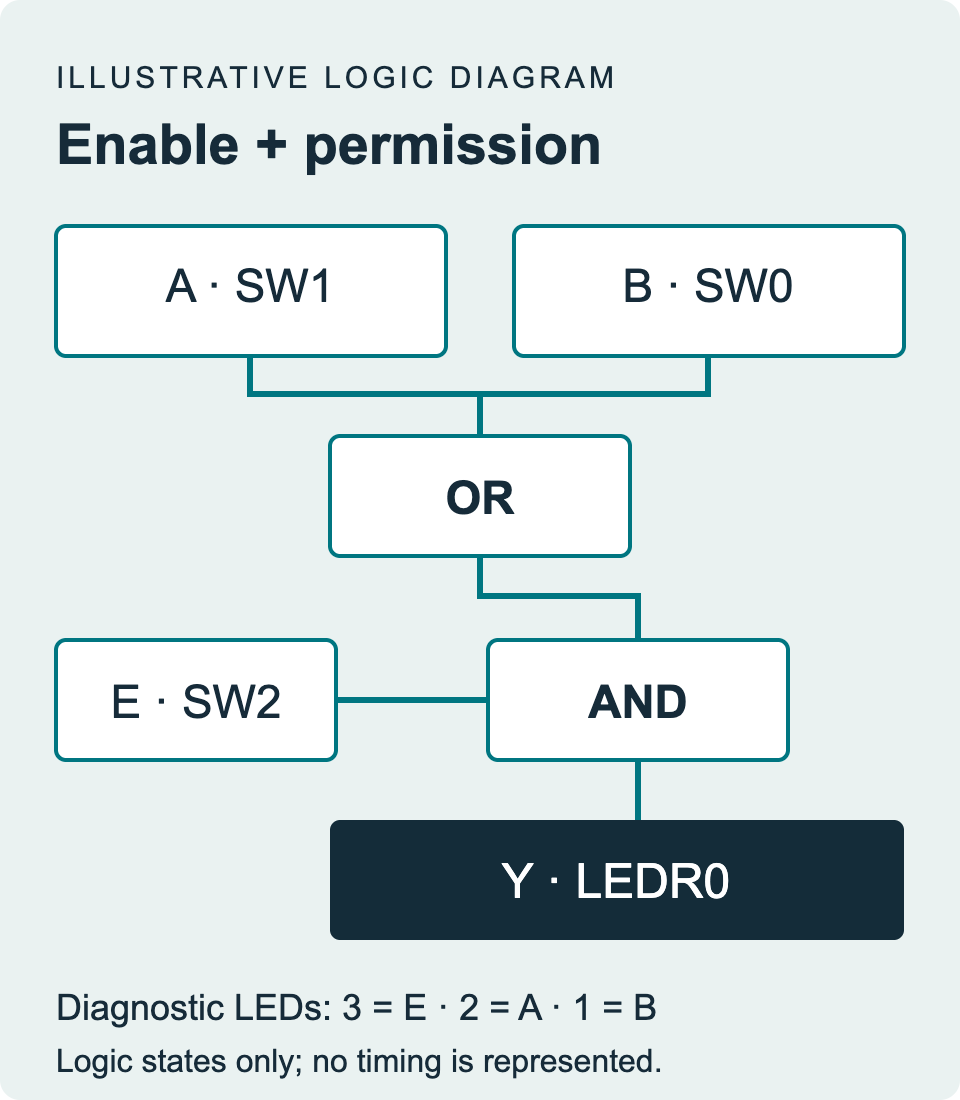
Teacher key: the expression is Y = E AND (A OR B). Only rows 101, 110 and 111 should light Y when the input order is E, A, B.
| E · SW2 | A · SW1 | B · SW0 | Expected Y · LEDR0 |
|---|---|---|---|
| 0 | 0 | 0 | 0 |
| 0 | 0 | 1 | 0 |
| 0 | 1 | 0 | 0 |
| 0 | 1 | 1 | 0 |
| 1 | 0 | 0 | 0 |
| 1 | 0 | 1 | 1 |
| 1 | 1 | 0 | 1 |
| 1 | 1 | 1 | 1 |
2. Implement the rule and make the inputs visible
Ask students to fill in the output expression in the student starter (PDF). The starter deliberately holds Y off, so successful compilation alone cannot complete the assignment.
The reference below uses continuous assignments. & and | are bitwise AND and OR; here each operand is one bit. The other three assigned LEDs mirror E, A and B. They are diagnostic outputs, not additional permission rules. All unused LEDs are explicitly driven off.
// Reference solution: E = SW[2], A = SW[1], B = SW[0].
// DE1-SoC Verilog Teach profile: keep file/module name leds_mirror.
module leds_mirror(input [9:0] SW, output [9:0] LEDR);
  assign LEDR[0] = SW[2] & (SW[1] | SW[0]);
  assign LEDR[3:1] = SW[2:0]; // E, A, B in switch order
  assign LEDR[9:4] = 6'b000000;
endmodule
The reference solution is public, so a correct implementation alone is not evidence of independent work. Ask students to justify the assignments, record their own observations and explain a test that exposes the faulty rule.
3. Build, upload and record all eight rows
Use Synthesize, resolve build errors, then select Upload to FPGA. Synthesis alone does not program the board. After every edit, synthesize and upload again before recording new observations.
- Set all switches off. Confirm the diagnostic LEDs agree with E = A = B = 0.
- Set all three relevant switches explicitly for each row, in the order 000, 001, 010, 011, 100, 101, 110, 111. Avoid instructions such as “then turn A on” that leave the previous B state ambiguous.
- Allow the camera view to settle. Record the observed Y value separately from the prediction. In this profile, the LEDs are active-high: lit means 1.
- For any mismatch, record the row, the code version and what you checked. Keep the original observation when you correct a transcription or implementation error.
- After the main table, vary an unused switch while holding E, A and B fixed. Explain why Y should not change.
With a correct design, Y stays off for the first five rows and lights for the last three. Record the stable LED states from the camera; this exercise does not measure switching speed.
4. Use one wrong expression to teach useful testing
Now show Y = (E AND A) OR B. Before anyone edits code, ask for a row where the two rules disagree. There are exactly two: EAB = 001 and 011. In both, B turns Y on while E is off, so B has bypassed the enable. The other six rows give the same output for both rules, including 111. A demonstration that only checks “everything on” cannot catch this mistake.
Students can explain this on paper or test the faulty expression, clearly labeling that run. If they upload it, they must restore their correct design and repeat the verification. A useful exit question is: “If you could run only one test to catch this error, which row would you choose, and why would 111 be a poor choice?”
5. Assess the evidence, not the screenshot alone
Request one compact submission: the final source file, the eight predicted and observed rows, two labeled camera captures: EAB = 001, plus one row assigned by the teacher from 101, 110 and 111, and a short explanation of the counterexample. The captions should identify switch settings, Y, the diagnostic LEDs and the code version. One capture with a lit LED cannot demonstrate the whole truth table.
| Criterion | Points | What earns full credit |
|---|---|---|
| Requirement and prediction | 4 | All eight predictions correct; the explanation distinguishes enable from permission. |
| Implementation | 4 | The expression implements the requirement; all outputs are defined and the input mapping is consistent. |
| Hardware evidence | 4 | Eight observed rows are recorded; the two captures support their labeled rows; any mismatch is documented. |
| Reasoning and debugging | 4 | The student explains why 001 or 011 exposes the faulty rule and why 111 does not. |
For each criterion, award 3 for a minor omission, 2 for a substantial but incomplete attempt, 1 for minimal relevant evidence and 0 for no evidence. Publish this 16-point scheme with the worksheet. If access fails, allow the prediction, code and debugging explanation to be submitted first; leave the hardware evidence pending rather than asking students to invent it.
Common mistakes worth discussing
- Reversing the input order. The table is EAB, which is SW2–SW1–SW0. Use the diagnostic LEDs to check the mapping.
- Testing an older upload. A new source file does not change the running circuit until the new build is uploaded.
- Treating compilation as correctness. Both the starter and the faulty expression can compile. The truth table tests the requirement.
- Using pushbuttons instead of switches. The documented DE1-SoC buttons have different polarity. This exercise deliberately uses switches only.
- Reporting expectations as observations. Keep the worksheet’s two columns separate, including when the camera is unreadable.
Download the student worksheet (PDF) · Download starter (PDF) · Download reference and test (PDF)
The reference was simulated with Icarus Verilog across all 1,024 switch settings. It has not been verified in a physical-board run.
Where to go next
For a guided introduction before this task, start with the Verilog first-gates lesson in Teach. Once students can connect a requirement, implementation and test, move to the truth-table and minimization lesson. Preview the lessons publicly, then sign in with your educator account to prepare a class session and check your lab access.